Five focused technical reading desks for recognizing what a connector is—and what its shape cannot tell you. Start with evidence. Continue with a safe next check.
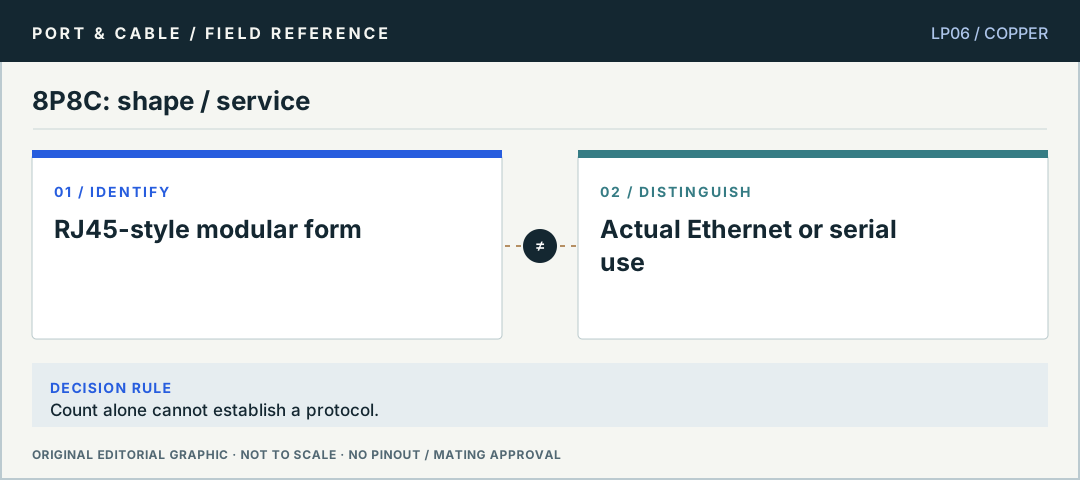
No. Read the equipment label and exact cable listing before treating a modular port as Ethernet, console or a powered connection. Even on a documented Ethernet cable, the protection rating can differ between its two ends.
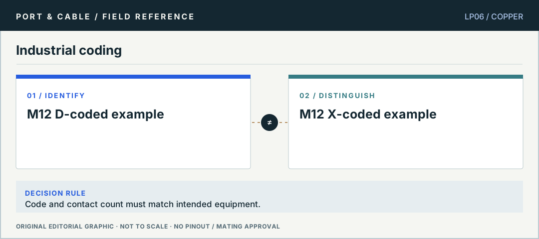
Phoenix Contact 1561797 documents a four-position D-coded M12-to-RJ45 cable at 100 Mbps. Its M12 end and RJ45 end have separate listed protection ratings. That evidence describes the cable, not an arbitrary port, PoE service or working network.
No. The cited 1851772 cable is an eight-position M12 X-coded male-to-female example listed for Ethernet CAT6A / 10 Gbps. A cable capability is not a host capability or an achieved link rate.
The illustrated 1453481 is a rear-mounted, four-position A-coded male device connector with free individual leads. It is a different procurement and installation role from a finished network patch lead.
No interchangeability follows from the shared position count. The retained Phoenix 1323169 observation identifies a four-position D-coded PROFINET/CAT5 example; the A-coded 1453481 is a separately documented device connector. A fresh retrieval of 1323169 was unavailable in this release.
Not reliably. Phoenix Contact lists 1836717 as an unshielded five-position A-coded sensor/actuator cable and offers several grip-body colors. The pictured yellow cable is a named example, not a color key for all M12 products.
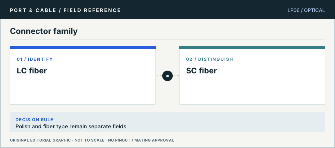
No. Connector body and polish are separate properties. The Fluke source warns against direct APC-to-UPC contact mating; a hybrid patch cord with each end matched to its own port is not the same situation.
The body name alone does not settle that. The retained Corning/Fluke evidence separates connector family from endface finish. Check the polish at each mating interface as well as the fiber and optic requirements.
The cited TE kit and receptacle evidence identify an ST-style bayonet connection role. They do not establish which fiber, polish or optical service an unknown lead carries, or that a passive mechanical join produces a suitable optical link.
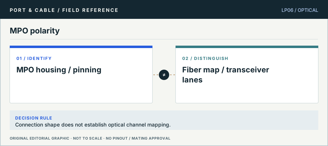
No. Fluke describes alignment guide pins separately from polarity methods that route transmit fibers to receive fibers. A physically plausible guide-pin pairing does not determine a complete link’s mapping, fiber count or optical support.
The host PCB connector and metal cage hold a removable module or supported cable assembly. Cisco’s optical and copper SFP examples have different network-facing connections. The SFP-family host shape does not select the medium or certify a module for a switch.
No. Amphenol’s ExpressPort listing distinguishes an SMT host connector from the associated press-fit cage. That mechanical product description is not a supported transceiver list or a guarantee of any particular network rate.
The cited V36-BAZ17-205E11A is a 2x1 long cage assembly with light pipes and a heatsink, intended for an anchor-pin SMT connector. That component description does not establish an included optical transceiver, compatible switch or operating network link.
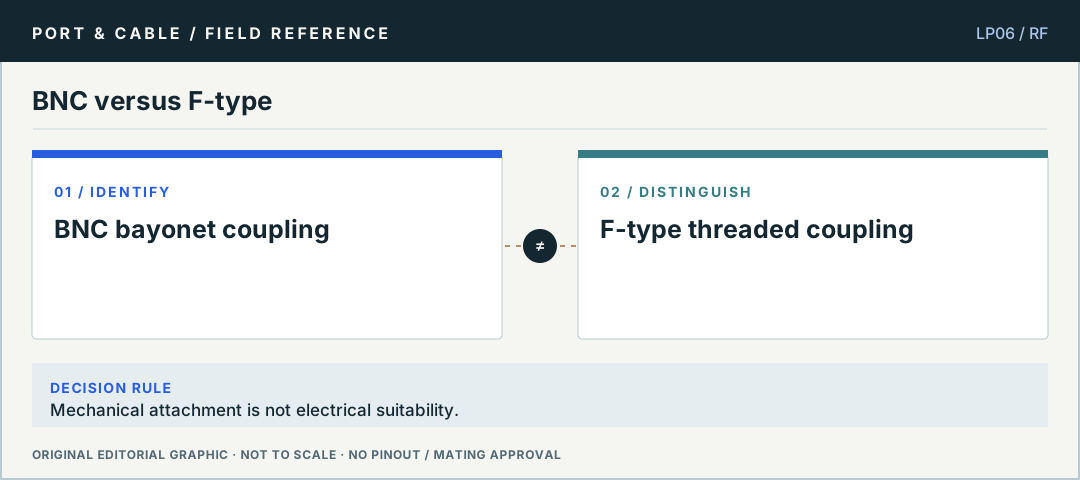
Yes. The retained Amphenol evidence warns that a mechanically mating 50-ohm/75-ohm mix can create an impedance discontinuity and reflections. Body fit is not a sufficient RF matching criterion.
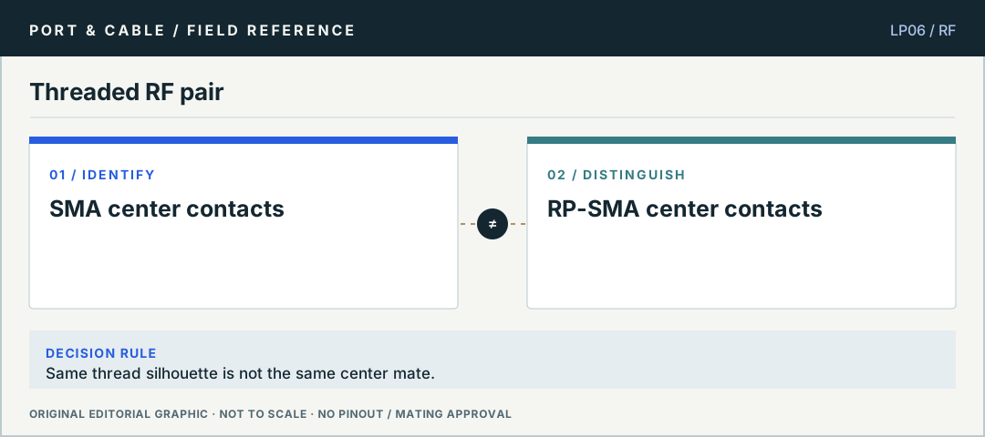
No. Confirm the center-contact convention as well as the coupling, exact part, cable and intended service. Amphenol also makes tightening guidance material-specific; this reference intentionally provides no universal torque instruction.
The center-contact convention is reversed relative to ordinary SMA while the outer threaded interface is retained. “Reverse polarity” here is not a statement that the RF signal is inverted, nor permission to connect any two matching shells.
The retained Hirose evidence distinguishes the board receptacle from specified plug variants and the height of their assembled pair. A standalone receptacle dimension cannot be reused as a universal installed cable-assembly height.
No. The retained I-PEX observations tie mated height to named plug and receptacle combinations and distinguish other MHF 4L examples. Keep the exact pair and drawing context rather than treating the family name as a universal clearance guarantee.
No: the type letter identifies a distinct form. Sony’s MRW-G2 instructions name CFexpress Type A; the MRW-G1 support statement instead names Type B and selected XQD series.
No. The shared Type B/XQD form needs a separate device-support check. Sony MRW-G1 is a named reader with documented support for both the specified Type B and XQD families.
Use a named card and reader pairing. Sony explicitly lists XQD G and M series for MRW-G1; the shared Type B form does not create a universal reader rule.
Not by itself. CompactFlash, CFast and CFexpress are separate standards. The recorded Transcend RDF8 sheets name CompactFlash UDMA7, not an all-CF-family reader.
The similar name hides a different interface: the CFA identifies CFast with Serial ATA and CompactFlash with Parallel ATA. Select the reader for the full family name.
No wiring or device match follows from contact count. NC3MXX is a full-size male XLR cable component; Switchcraft TA3MLX is a separate Mini-XLR component.
For Neutrik NL2FXX-W-S, the manufacturer documents that mating path using +1/-1. This is a component statement, not approval of the amplifier and speaker wiring.
Not for the named NL2MPXX chassis example: Neutrik explicitly excludes a four-pole cable connector. Keep cable and chassis roles visible in any comparison.
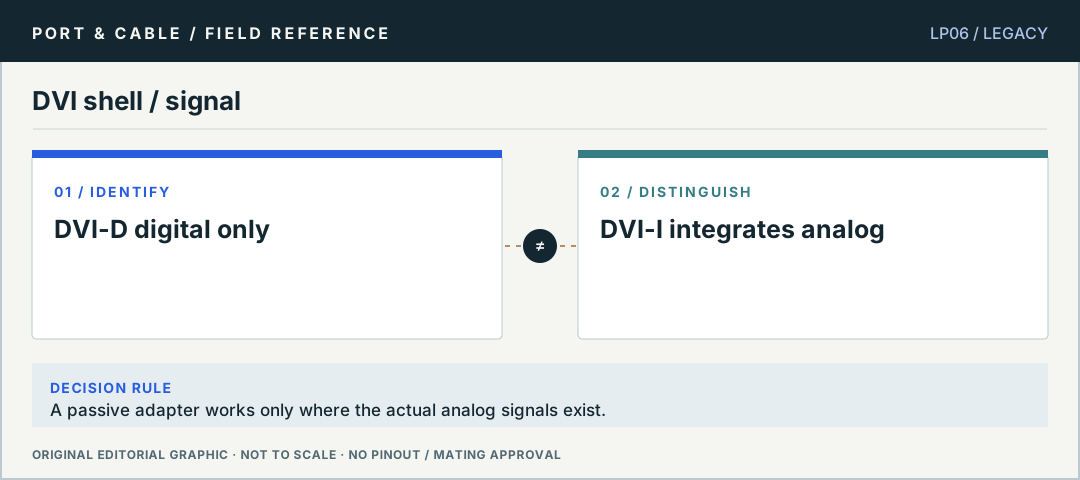
DVIVGAMF is a named passive DVI-I-to-VGA adapter. Its pictured dual-link-shaped DVI-I plug is not proof of a digital dual-link mode or compatibility with every DVI-I output.
DVI2VGAE documents DVI input and VGA output. That evidence does not establish VGA-source-to-DVI-display operation. Its hardware table also excludes audio.
The six-pin interface includes DC power as well as data, unlike the four-pin form. Actual power availability and software support still depend on the equipment.
Are you identifying a housing, a signal standard, a cable assembly, or a whole device path? Those are four different facts. This reference shows which one the available evidence actually supports.