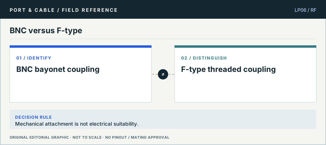
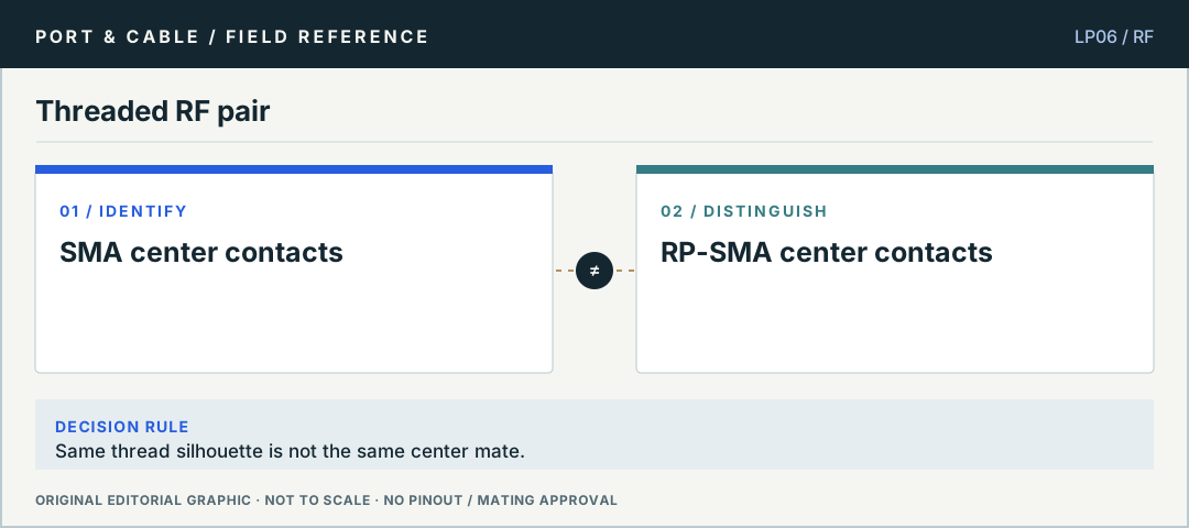
BNC versus F-typeMechanical attachment is not electrical suitability. Original editorial logic plate, not verified mating geometry or a physical pinout.Threaded RF pairSame thread silhouette is not the same center mate. Original editorial logic plate, not verified mating geometry or a physical pinout.
03 / TASK NOTES
Questions you can answer before buying a cable
Direct answers, consequences of getting it wrong, exact next checks and links to the registered canonical evidence.
01 / P027
BNC fit does not establish impedance
Can a 50-ohm BNC be used on a 75-ohm video path?
ANSWER FIRST
Amphenol RF documents both 50-ohm and 75-ohm BNC variants. Mechanical attachment does not by itself mean a path is impedance-matched for the signal or frequency.
Three checks before deciding
Read the exact connector model and impedance.
Check the coax cable characteristic impedance.
Confirm the device port and application requirements.
Only the narrow canonical source claims listed below are registered evidence. The cautionary next checks are educational method, not a field safety approval.
C027A — BNC uses a bayonet coupling; both 50-ohm and 75-ohm variants exist.
C027C — Amphenol RF documents BNC as a bayonet-coupled interface family with both 50-ohm and 75-ohm variants and MIL-STD-348 interface context; connector variant and system impedance still must be resolved for the actual path.
No. Amphenol describes F-type as a threaded 75-ohm family; BNC is bayonet-coupled and has multiple impedance variants. The equipment connector, coax and termination must be specified.
Three checks before deciding
Confirm the connector family and equipment port.
Check cable construction and installation instructions.
Use an adapter only if signal path requirements are met.
Only the narrow canonical source claims listed below are registered evidence. The cautionary next checks are educational method, not a field safety approval.
C065A — Amphenol describes its F-type family as a threaded 75-ohm interface used for CATV and broadband connections. A family name does not establish every cable assembly or installation requirement.
C065B — Amphenol RF documents F-Type as a 75-ohm coaxial connector family using threaded coupling; connector configuration and cable choice still determine actual performance.
Why can two threaded antenna connectors fail to mate?
ANSWER FIRST
Amphenol distinguishes SMA from RP-SMA by the center-contact arrangement. Similar outer threading does not prove that both contacts will engage correctly.
Three checks before deciding
Inspect manufacturer-defined contact arrangements without force.
Verify the complete SMA or RP-SMA variant.
Check frequency, impedance, cable and antenna connector requirements.
Only the narrow canonical source claims listed below are registered evidence. The cautionary next checks are educational method, not a field safety approval.
C064A — RP-SMA changes the center-contact arrangement relative to ordinary SMA while retaining the same threaded interface. The RP prefix is not a claim that a signal is electrically inverted.
C064B — Amphenol RF describes RP-SMA as reversing the center-contact gender relative to SMA while retaining the SMA-style threaded interface; shell appearance alone is therefore insufficient to identify the center-contact arrangement.
Is an N-Type antenna plug a safe substitute for SMA?
ANSWER FIRST
N-Type and SMA are distinct RF connector families with different interfaces. Adaptation requires a specified connector pair and equipment/cable analysis; bigger threads mean nothing about signal fitness.
Three checks before deciding
Identify each interface by manufacturer designation.
Check correct coupler or adapter family.
Validate cable/impedance and RF power requirements.
Only the narrow canonical source claims listed below are registered evidence. The cautionary next checks are educational method, not a field safety approval.
C224A — Amphenol RF identifies N-Type as a threaded RF coaxial connector family.
No. Hirose U.FL and I-PEX MHF I/MHF 4 are distinct product families. The exact plug, receptacle, cable outer diameter and intended mated height must be confirmed from makers.
Only the narrow canonical source claims listed below are registered evidence. The cautionary next checks are educational method, not a field safety approval.
C353A — Hirose specifies U.FL as a miniature SMT micro-coaxial series with nominal series mated-height variants; one label does not fix a universal height or RF limit.
C353C — The U.FL catalog depicts U.FL-R-SMT-1 as a board receptacle; its stand-alone receptacle view is not a complete plug-and-receptacle mated-height drawing.