FIELD GUIDESource-led reference

P125 / Fiber / Connector

MPO multi-fiber connector

MPO combines multiple fibers in one connector family; fiber count, pin configuration and polarity remain separate requirements.

Also called MPO multi fiber push on MPO polarity

MPO is not one universal optical cable.

Look for

Record MPO from the equipment or cable label. Use documentation for pin configuration and polarity; do not inspect the optical end by eye.

Claim inspection dates: 2026-10-03, 2026-10-11, 2026-10-22 · Independent review pending

Image inspection / P125

See the view. Check its scope.

2 registered views for this reference. Different part examples are not automatically mates; all remain not to scale and independently unapproved.

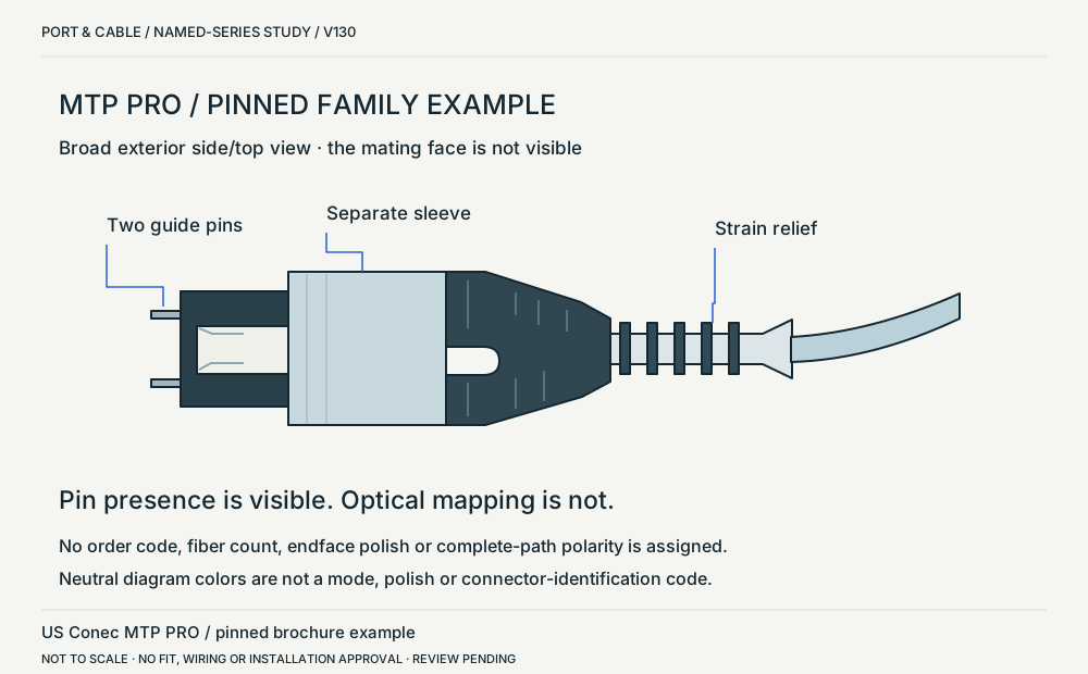
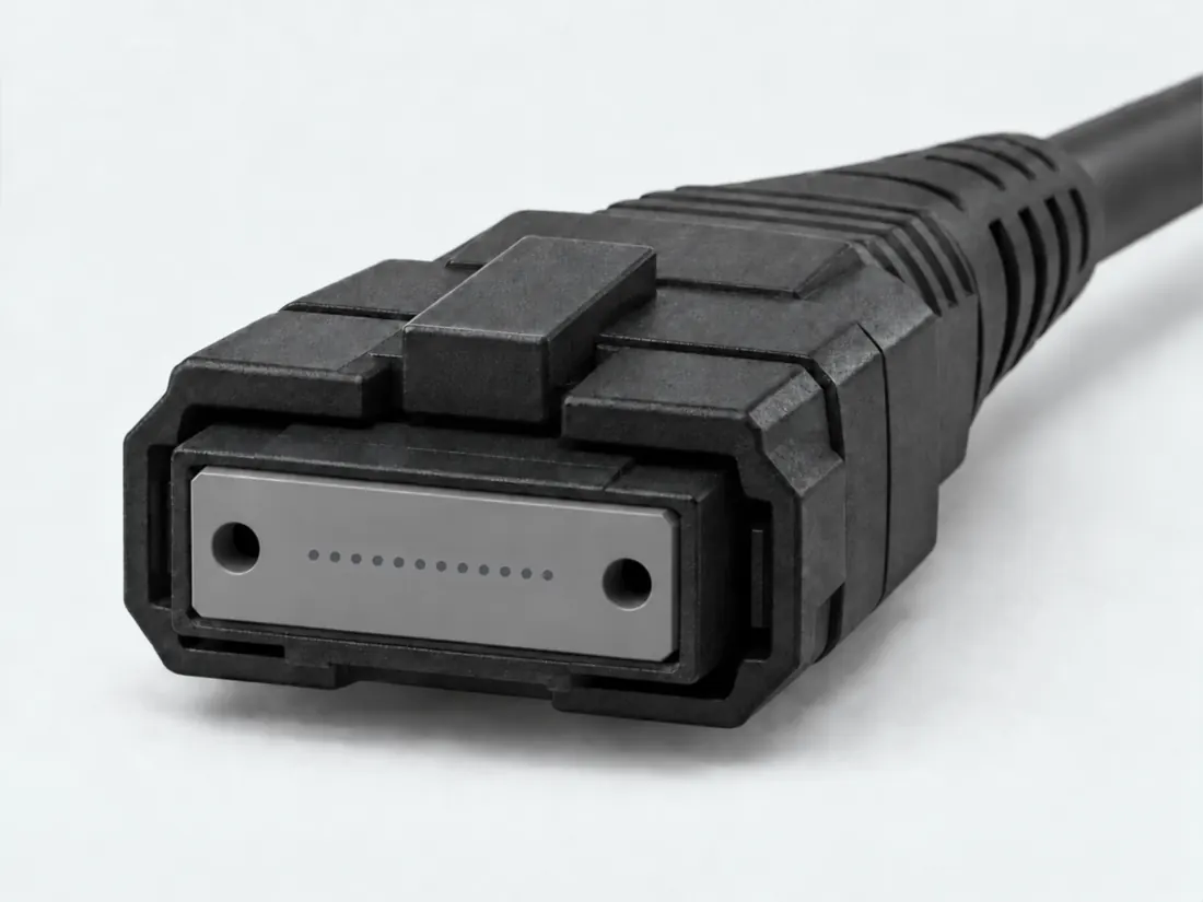
MTP PRO / pinned family exterior. Cover photograph, broad exterior side/top view; not a mating-face view. Visible guide pins to the left, sleeve in the middle, strain relief and cable to the right. No dimensional, wiring or compatibility approval. (private workspace)

P125 / Source-observed physical study

MTP PRO / pinned family exterior

US Conec MTP PRO / pinned brochure example

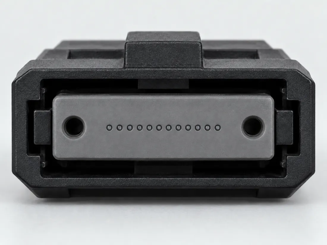
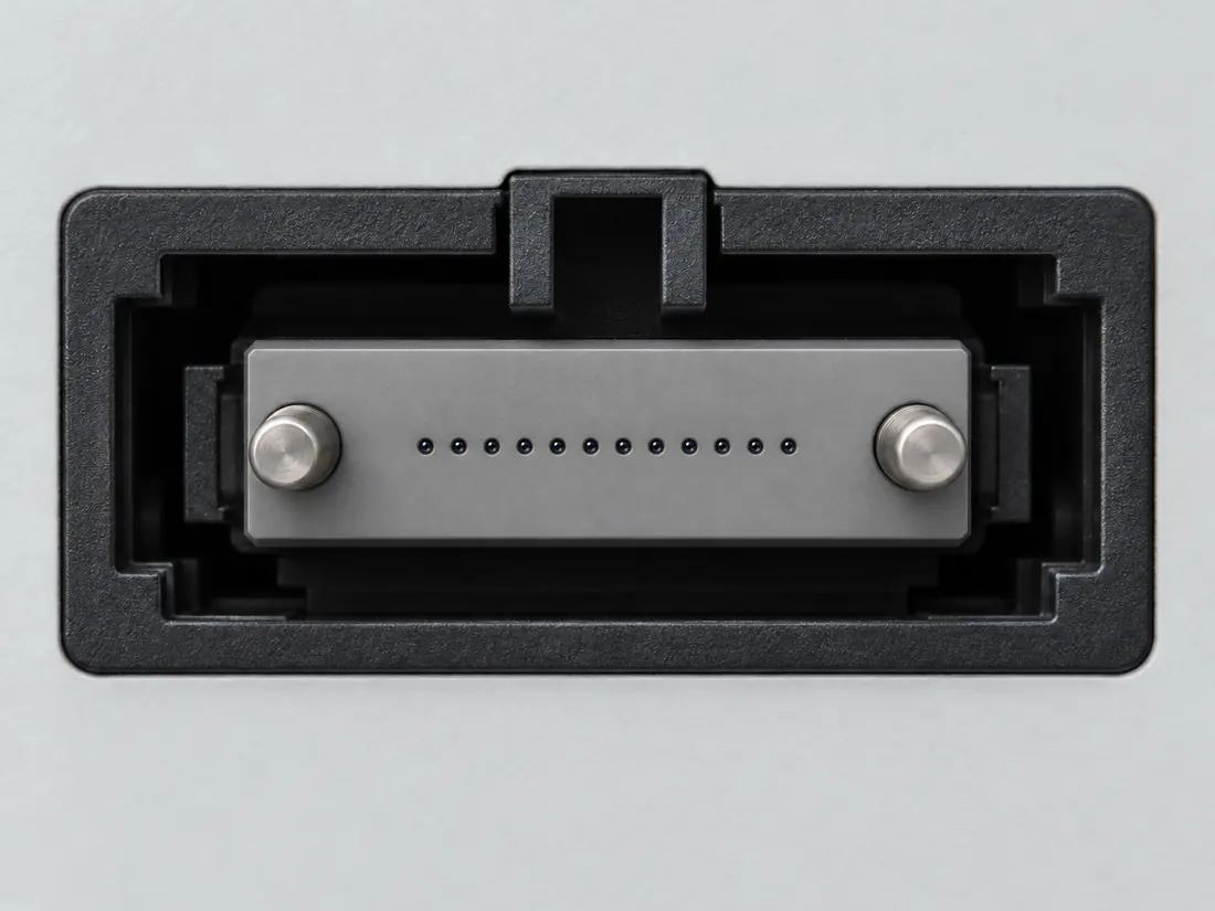
Cover photograph, broad exterior side/top view; not a mating-face view. · Cable plug / cable end

Not to scale. Technical and rights review pending.

Inspect view & provenance (private workspace)
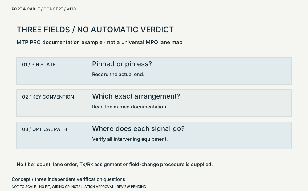
Pins / keys / optical path. Abstract text-and-symbol dependency map, not a fiber-lane map. Three separate reading panels; no physical orientation or mating face. No dimensional, wiring or compatibility approval. (private workspace)

P125 / Concept — not physical geometry

Pins / keys / optical path

Concept / three independent verification questions

Abstract text-and-symbol dependency map, not a fiber-lane map. · Concept only

Not to scale. Technical and rights review pending.

Inspect view & provenance (private workspace)

Network notes / Fiber / P125

Do MPO guide pins establish the fiber mapping?

FIELD NOTES 05

No. Guide-pin roles concern alignment; polarity concerns the transmit/receive mapping through the complete link. A complementary pair of guide-pin roles settles neither the fiber count nor that mapping. C125C

Component or signal: documented distinction and remaining check
CheckDocumented distinctionWhat this does not establish
AlignmentFluke distinguishes pinned male and pinless female MPO roles. C125CThis is not permission to assume the counterpart on unidentified equipment.
PolarityThe same reference treats transmit/receive fiber mapping as a separate requirement. C125CRead the complete documented path, including trunks and adapters, not just one key or shell.
Inspection boundaryCisco warns against viewing energized fibers or using unfiltered magnifiers. C125BDo not identify polarity by looking into a live endface.
Read the part and the device.
Read the connector pin/pinless role, fiber-count family and cable polarity designation. Treat these as different fields, not interchangeable names.
Keep this requirement open.
The required Base-8/Base-12 or other topology, polarity, key orientation, optic and full path are not established from a shell photograph.

Keep this limit: No field pin conversion, key reversal, full Base-8/Base-12 path or optical performance is approved from these observations. C125C · C125B

Not established · named example only

Do complementary MPO guide-pin roles prove correct polarity?

No full fiber mapping is established by alignment-pin roles alone.

Boundary. Guide pins and polarity are different fields; an actual complete path was not tested.

Next check. Check the documented trunk, adapters, optic and polarity method together.

S505 · C125C (private workspace)

Before choosing the cable or component

  1. Record the optic, trunk and adapter part numbers and documented fiber topology.
  2. Check guide-pin roles separately from the complete link’s polarity method.
  3. Use the vendor’s specified path and optical-safety process; no live endface viewing.

Source check · 14 October 2026. Fluke’s alignment/mapping distinction and Cisco’s safety warning were re-observed. The inherited MTP PRO reconfiguration brochure was not rechecked.

Source-qualified reference, not a wiring, optical-link or compatibility approval. Each linked claim and source carries its own recorded inspection date and review status. Selected source checks do not constitute independent technical or rights approval.

Existing source trail: S505 · S104.

Network, fiber and RF questions

Read the evidence and its scope · 3 observations

C125A (private workspace) — Fluke describes MPO as a multi-fiber push-on connector and documents different polarity and pin configurations.

Identification and explicitly scoped documentation only; not an end-to-end connection approval

S100

C125B (private workspace) — Cisco warns against looking into energized fibers or inspecting them with unfiltered magnifiers.

Identification and explicitly scoped documentation only; not an end-to-end connection approval

S104

C125C (private workspace) — Fluke Networks distinguishes MPO male guide pins and female pinless connectors from polarity methods that map transmit fibers to receive fibers. Matching guide-pin roles alone does not establish the fiber mapping of a link.

V121 named-product or explicitly scoped manufacturer distinction only; no wiring instruction, independent engineering approval or end-to-end compatibility guarantee.

S505

Source interpretation is not independent engineering review, hardware testing, wiring advice or a public-release approval.

V117 / READER FIELD GUIDE / FIBER IDENTITIES

Before you connect or replace

MPO adds fiber-map and gender questions

No. MPO identifies a multifiber connector form; pin/gender and polarity mapping remain separate choices. Verify the entire cassette/trunk/transceiver path rather than assuming a matching shell fixes polarity.

Three checks and exact source trail ↗

Editorial decision guidance only. A connector identity or nominal pitch does not establish approved mating, safe wiring or a supported device combination.

The useful distinction

Recognize it. Then verify it.

MPO combines multiple fibers in one connector family; fiber count, pin configuration and polarity remain separate requirements. [C125A]

Cisco warns against looking into energized fibers or inspecting them with unfiltered magnifiers. [C125B]

Fluke Networks distinguishes MPO male guide pins and female pinless connectors from polarity methods that map transmit fibers to receive fibers. Matching guide-pin roles alone does not establish the fiber mapping of a link. [C125C]

US Conec’s MTP PRO brochure lists pin reconfiguration and polarity reconfiguration as separate features of that product family. [C125D]

The MTP PRO brochure’s polarity example distinguishes a Type A key-up/key-down cable arrangement from Type B key-up/key-up after a key-orientation change. [C125E]

The MTP PRO brochure distinguishes black exposed key as factory polarity setting and white exposed key as field-configured setting; its permanent keys are separate from guide-pin configuration. [C125F]

US Conec describes its MTP PRO DirectConec push-pull system at the integrated strain-relief boot; pin-clamp and key-color information concern different components. [C125G]

Source-scoped identification facts

Each value retains its exact example, role and measurement axis. Facts from different parts must not be combined into an invented component.

Documented examples; not a mating drawing or compatibility approval
Connector roleMPO-format optical cable connector (Named series/reference only, not every family part. USConec MTP PRO manufacturer-series;not universalMPOformat)S953Current primary-source scoped values; named examples remain separate and unknowns are not inferred from illustrations. Named series/reference only, not every family part. USConec MTP PRO manufacturer-series;not universalMPOformat
Coupling / latchDirectConec push-pull via integrated strain-relief boot (Named series/reference only, not every family part. USConec MTP PRO manufacturer-series;not universalMPOformat)S953Current primary-source scoped values; named examples remain separate and unknowns are not inferred from illustrations. Named series/reference only, not every family part. USConec MTP PRO manufacturer-series;not universalMPOformat
Keying / polarizationTwo permanentlymounted keys;exposedkey identifies factory/fieldsetting in thisproduct (Named series/reference only, not every family part. USConec MTP PRO manufacturer-series;not universalMPOformat)S953Current primary-source scoped values; named examples remain separate and unknowns are not inferred from illustrations. Named series/reference only, not every family part. USConec MTP PRO manufacturer-series;not universalMPOformat
ManufacturerUS Conec (Named series/reference only, not every family part. USConec MTP PRO manufacturer-series;not universalMPOformat)S953Current primary-source scoped values; named examples remain separate and unknowns are not inferred from illustrations. Named series/reference only, not every family part. USConec MTP PRO manufacturer-series;not universalMPOformat
SeriesMTP PRO (Named series/reference only, not every family part. USConec MTP PRO manufacturer-series;not universalMPOformat)S953Current primary-source scoped values; named examples remain separate and unknowns are not inferred from illustrations. Named series/reference only, not every family part. USConec MTP PRO manufacturer-series;not universalMPOformat
Recorded markingsBlack exposedkey=factorysetting;white exposedkey=fieldconfigured setting. Pin-clamp color table has a different meaning. (Named series/reference only, not every family part. USConec MTP PRO manufacturer-series;not universalMPOformat)S953Current primary-source scoped values; named examples remain separate and unknowns are not inferred from illustrations. Named series/reference only, not every family part. USConec MTP PRO manufacturer-series;not universalMPOformat
View conventionBrochurepages1-3exterioroblique sourcephotographs and labelledkeyillustrations actuallyviewed;no dimensionedface map (Named series/reference only, not every family part. USConec MTP PRO manufacturer-series;not universalMPOformat)S953Current primary-source scoped values; named examples remain separate and unknowns are not inferred from illustrations. Named series/reference only, not every family part. USConec MTP PRO manufacturer-series;not universalMPOformat

Not recorded: Dimensions / axis, Mounting, Shell / form, Exact part / implementation. Unknown fields stay unknown; illustrations supply no measurements or pin assignments.

Report a correction to these facts →

Bounded facts, visible unknowns

Specifications and limits

MPO multi-fiber connector facts and limitations
Documented identificationFluke describes MPO as a multi-fiber push-on connector and documents different polarity and pin configurations. [C125A]
Important distinctionCisco warns against looking into energized fibers or inspecting them with unfiltered magnifiers. [C125B]
Mechanical dimensionsNo independently approved mechanical dimensions. Do not use this record for fabrication or fit testing.
Engineering pinoutSource-checked engineering profile available; independent review pending. Open engineering profile →
Verified device listNot included. Check exact device and accessory documentation.
A boundary, not an omission to guess around.

Record the exact device model and the label beside the port. Obtain its manual and the accessory documentation. Keep unknown properties unknown instead of filling them from a visually similar item.

Before you connect

What to check

  1. Check the documented fiber count and pinned/unpinned ends.
  2. Read the required polarity and cable type from the system documentation.
  3. Keep the optical safety boundary and avoid trial-fitting an unknown link.
Trace a supported connection class →

What is not established

This field note does not approve a connection, publish a pinout or provide a measured template. Use the linked source scope and the checklist as a documentation starting point.

Your next step

Move from the form to the requirement.

The source trail

Evidence for this page

AI-assisted inspection is not independent engineering review. Source scope and access limitations are disclosed below. Procedural checklists are editorial requirements, not hardware measurements.

Back to first citation ↑
C125ASource checked · pending review

Fluke describes MPO as a multi-fiber push-on connector and documents different polarity and pin configurations.

Fluke Networks · MultiFiber Pro — MPO documentation ↗

Locator: Overview; Built-in Polarity Verification; Accessories
Access: public page. No loss limits, transceiver support or universal fiber count. This is product documentation, not a complete connector standard.

S100: full source recordInspect review dependencies → (private workspace)

Claim scope: Identification and explicitly scoped documentation only; not an end-to-end connection approval. Next review due 2027-01-01.

Back to first citation ↑
C125BSource checked · pending review

Cisco warns against looking into energized fibers or inspecting them with unfiltered magnifiers.

Cisco · Fiber-optic inspection safety boundaries ↗

Locator: Warnings
Access: public page. V12 does not reproduce or authorize cleaning, live inspection, loss testing or optical engineering procedures.

S104: full source recordInspect review dependencies → (private workspace)

Claim scope: Identification and explicitly scoped documentation only; not an end-to-end connection approval. Next review due 2027-01-01.

Back to first citation ↑
C125CSource checked · pending review

Fluke Networks distinguishes MPO male guide pins and female pinless connectors from polarity methods that map transmit fibers to receive fibers. Matching guide-pin roles alone does not establish the fiber mapping of a link.

Fluke Networks · Fluke Networks — MPO guide pins and polarity are different checks ↗

Locator: 6 January 2026 article; MPO connector types; 12- and 8-fiber polarity methods
Access: public page. Guide-pin presence and fiber mapping are distinct properties. Article concerns its described Base-8/Base-12 examples, not every MPO system. No raw HTML or manufacturer image archive is represented as retained.

S505: full source recordInspect review dependencies → (private workspace)

Claim scope: V121 named-product or explicitly scoped manufacturer distinction only; no wiring instruction, independent engineering approval or end-to-end compatibility guarantee.. Next review due 2027-01-09.

Back to first citation ↑
C125DSource checked · pending review

US Conec’s MTP PRO brochure lists pin reconfiguration and polarity reconfiguration as separate features of that product family.

US Conec · MTP PRO Solutions brochure SM-0024-0721 ↗

Locator: 2021 brochure; printed p.1 exterior photograph and separate pin/polarity features; p.3 key-orientation example.
Access: public pdf text. MTP PRO family only. The cover image has no ordered part, fiber-count or polish selection. No general MPO wiring prescription or full-link polarity result.

S531: full source recordInspect review dependencies → (private workspace)

Claim scope: Named MTP PRO design only, not a claim that all MPO connectors can be reconfigured or that visible pins establish transmit/receive mapping.. Next review due 2027-01-09.

Back to first citation ↑
C125ESource checked · pending review

The MTP PRO brochure’s polarity example distinguishes a Type A key-up/key-down cable arrangement from Type B key-up/key-up after a key-orientation change.

US Conec · MTP PRO Solutions brochure SM-0024-0721 ↗

Locator: 2021 brochure; printed p.1 exterior photograph and separate pin/polarity features; p.3 key-orientation example.
Access: public pdf text. MTP PRO family only. The cover image has no ordered part, fiber-count or polish selection. No general MPO wiring prescription or full-link polarity result.

S531: full source recordInspect review dependencies → (private workspace)

Claim scope: That documented cable/key convention only. It is not a fiber-lane diagram, an end-to-end polarity approval or an instruction to alter a live cable.. Next review due 2027-01-09.

Back to first citation ↑
C125FSource checked · pending review

The MTP PRO brochure distinguishes black exposed key as factory polarity setting and white exposed key as field-configured setting; its permanent keys are separate from guide-pin configuration.

US Conec · MTP PRO Solutions brochure SM-0024-0721 ↗

Locator: Full4-page PDF text and actual150dpi pages1-3pixels: p.1DirectConecpush-pull;p.2pin-clamp color table;p.3permanentkeys,color and polarity illustrations.
Access: public pdf text. No universal MPO fiber count,pitch,interface dimensions or optical mapping inferred. Pin-clamp colors and exposed-key colors have different meanings. No source adjustment/service procedure is reproduced.

S953: full source recordInspect review dependencies → (private workspace)

Claim scope: USConec MTP PRO manufacturer-series;not universalMPOformat only;not a genericMPOcolorcode,fibercount orcomplete linkpolarity guarantee.. Next review due 2027-01-20.

Back to first citation ↑
C125GSource checked · pending review

US Conec describes its MTP PRO DirectConec push-pull system at the integrated strain-relief boot; pin-clamp and key-color information concern different components.

US Conec · MTP PRO Solutions brochure SM-0024-0721 ↗

Locator: Full4-page PDF text and actual150dpi pages1-3pixels: p.1DirectConecpush-pull;p.2pin-clamp color table;p.3permanentkeys,color and polarity illustrations.
Access: public pdf text. No universal MPO fiber count,pitch,interface dimensions or optical mapping inferred. Pin-clamp colors and exposed-key colors have different meanings. No source adjustment/service procedure is reproduced.

S953: full source recordInspect review dependencies → (private workspace)

Claim scope: USConec MTP PRO manufacturer-series;not universalMPOformat;identificationcontext,not aninstructiontoreconfigure a live opticalpath.. Next review due 2027-01-20.

Suggest a correction to this field note →
Put this field note to work.

Add to discovery trayRecord an unsaved candidate (private workspace)

Candidate selection does not confirm the identity or capabilities of your physical item.

SOURCE-QUALIFIED FIBER REFERENCE

Identify the end. Keep the path unresolved.

US Conec MTP PRO pinned cover example

Source / component role
Named-series exterior photograph, not a mating-face view
Documented distinction
The brochure describes separate pin and polarity reconfiguration features.
What this establishes
Two visible guide pins identify the depicted example’s pin state, not its fiber count or complete-link polarity.
Not established
Ordered part, endface polish, both cable ends, transceivers and optical mapping.
Next check
Record pin state and exact family first; then verify the documented key and full optical path.
Inspect the declared view → (private workspace)
Evidence, observation & limits

Inspected . C125D

MTP PRO Solutions brochure SM-0024-0721 ↗
V130 observation: 2021 brochure; printed p.1 exterior photograph and separate pin/polarity features; p.3 key-orientation example.
Canonical source record S531 dated 2026-10-11. The V130 visit is recorded separately; inherited source dates are unchanged.

No hardware test, independent technical approval or rights clearance is asserted.

MTP PRO Type A / Type B key convention

Source / component role
Brochure-specific cable-key example
Documented distinction
The source’s Type A example is key-up/key-down; Type B is key-up/key-up.
What this establishes
That key convention does not supply a fiber-lane or transmit/receive diagram for the user’s installation.
Not established
All intervening trunks, cassettes, patch cords, transceivers and mapping.
Next check
Use the complete documented path; do not change a connector from this concept diagram.
Inspect the declared view → (private workspace)
Evidence, observation & limits

Inspected . C125E

MTP PRO Solutions brochure SM-0024-0721 ↗
V130 observation: 2021 brochure; printed p.1 exterior photograph and separate pin/polarity features; p.3 key-orientation example.
Canonical source record S531 dated 2026-10-11. The V130 visit is recorded separately; inherited source dates are unchanged.

No hardware test, independent technical approval or rights clearance is asserted.

Read the illustrated fiber chart and field guide →

Evidence behind this page

Scope first. Source second. Approval separate.

5 linked sources · 7 scoped claims · 0 sources with inspection/access flags.

Page scope: consumer_reference_expansion

Assessment 2026-10-22 · earliest scheduled source review 2027-01-01. This is a recorded-date assessment, not a live source check. Page-level independent review is not established by this panel.

Inspect 5 source scopes, access limits and dates

S100 · MultiFiber Pro — MPO documentation

Fluke Networks · Manufacturer / product-owner domain · inspected 2026-10-03 · due 2027-01-01

Within inspection window

Scoped support: MPO means multi-fiber push-on; polarity and pinned/unpinned configurations are separate properties.

Not established / limitations: No loss limits, transceiver support or universal fiber count. This is product documentation, not a complete connector standard.

Locator: Overview; Built-in Polarity Verification; Accessories

S104 · Fiber-optic inspection safety boundaries

Cisco · Manufacturer / product-owner domain · inspected 2026-10-03 · due 2027-01-01

Within inspection window

Scoped support: Do not look into energized fiber or use unfiltered magnifiers to inspect optical connectors.

Not established / limitations: V12 does not reproduce or authorize cleaning, live inspection, loss testing or optical engineering procedures.

Locator: Warnings

S505 · Fluke Networks — MPO guide pins and polarity are different checks

Fluke Networks · Manufacturer / product-owner domain · inspected 2026-10-11 · due 2027-01-09

Within inspection window

Scoped support: Guide-pin presence and fiber mapping are distinct properties. Article concerns its described Base-8/Base-12 examples, not every MPO system.

Not established / limitations: Guide-pin presence and fiber mapping are distinct properties. Article concerns its described Base-8/Base-12 examples, not every MPO system. No raw HTML or manufacturer image archive is represented as retained.

Locator: 6 January 2026 article; MPO connector types; 12- and 8-fiber polarity methods

S531 · MTP PRO Solutions brochure SM-0024-0721

US Conec · Unclassified publisher domain · inspected 2026-10-11 · due 2027-01-09

Within inspection window

Scoped support: MTP PRO family only. The cover image has no ordered part, fiber-count or polish selection. No general MPO wiring prescription or full-link polarity result.

Not established / limitations: MTP PRO family only. The cover image has no ordered part, fiber-count or polish selection. No general MPO wiring prescription or full-link polarity result.

Locator: 2021 brochure; printed p.1 exterior photograph and separate pin/polarity features; p.3 key-orientation example.

S953 · MTP PRO Solutions brochure SM-0024-0721

US Conec · Unclassified publisher domain · inspected 2026-10-22 · due 2027-01-20

Within inspection window

Scoped support: MTP PRO manufacturer-series example only; guide-pin configuration,permanentkey setting and optical polarity remain separate.

Not established / limitations: No universal MPO fiber count,pitch,interface dimensions or optical mapping inferred. Pin-clamp colors and exposed-key colors have different meanings. No source adjustment/service procedure is reproduced.

Locator: Full4-page PDF text and actual150dpi pages1-3pixels: p.1DirectConecpush-pull;p.2pin-clamp color table;p.3permanentkeys,color and polarity illustrations.

Trace 7 claims to their source records

C125A · P125

Fluke describes MPO as a multi-fiber push-on connector and documents different polarity and pin configurations.

Claim scope: Identification and explicitly scoped documentation only; not an end-to-end connection approval

Source links: S100 · Evidence trail → (private workspace)

C125B · P125

Cisco warns against looking into energized fibers or inspecting them with unfiltered magnifiers.

Claim scope: Identification and explicitly scoped documentation only; not an end-to-end connection approval

Source links: S104 · Evidence trail → (private workspace)

C125C · P125

Fluke Networks distinguishes MPO male guide pins and female pinless connectors from polarity methods that map transmit fibers to receive fibers. Matching guide-pin roles alone does not establish the fiber mapping of a link.

Claim scope: V121 named-product or explicitly scoped manufacturer distinction only; no wiring instruction, independent engineering approval or end-to-end compatibility guarantee.

Source links: S505 · Evidence trail → (private workspace)

C125D · P125

US Conec’s MTP PRO brochure lists pin reconfiguration and polarity reconfiguration as separate features of that product family.

Claim scope: Named MTP PRO design only, not a claim that all MPO connectors can be reconfigured or that visible pins establish transmit/receive mapping.

Source links: S531 · Evidence trail → (private workspace)

C125E · P125

The MTP PRO brochure’s polarity example distinguishes a Type A key-up/key-down cable arrangement from Type B key-up/key-up after a key-orientation change.

Claim scope: That documented cable/key convention only. It is not a fiber-lane diagram, an end-to-end polarity approval or an instruction to alter a live cable.

Source links: S531 · Evidence trail → (private workspace)

C125F · P125

The MTP PRO brochure distinguishes black exposed key as factory polarity setting and white exposed key as field-configured setting; its permanent keys are separate from guide-pin configuration.

Claim scope: USConec MTP PRO manufacturer-series;not universalMPOformat only;not a genericMPOcolorcode,fibercount orcomplete linkpolarity guarantee.

Source links: S953 · Evidence trail → (private workspace)

C125G · P125

US Conec describes its MTP PRO DirectConec push-pull system at the integrated strain-relief boot; pin-clamp and key-color information concern different components.

Claim scope: USConec MTP PRO manufacturer-series;not universalMPOformat;identificationcontext,not aninstructiontoreconfigure a live opticalpath.

Source links: S953 · Evidence trail → (private workspace)

Prepare this page for review → (private workspace)Read the evidence method →

Recorded evidence only. An inspection date, publisher label, source link or generated packet is not independent technical review, hardware testing, fabrication approval or a compatibility verdict.