FIELD GUIDESource-led reference
The field guide / 01 — The exact part

Manufacturer series & miniature ribbon

A pitch number is not a mating standard. See exact Molex, Hirose and TE Connectivity part identities with five newly source-gated canonical records.

01 / IDENTITY MATRIX

What actually distinguishes these forms

Exact recordDocumented role or clueNot established
Molex Mini-Fit Jr. ↗P3584.20 mm nominal familyMolex 874272002 is one 20-circuit right-angle example; verify the mating series and power harness
Molex Micro-Fit 3.0 ↗P3593.00 mm nominal familyMolex 430451200 is one 12-circuit dual-row right-angle example; not Mini-Fit Jr.
Hirose DF13 ↗P3601.25 mm nominal familyNot automatically JST GH; verify housing, crimp terminal and header
TE 1-2492111-7 top contact ↗P3610.5 mm; 17-position exampleTop-contact right-angle ZIF; cable face and count must match
TE 1-2492104-0 bottom contact ↗P3620.5 mm; 10-position exampleBottom-contact right-angle ZIF; not a generic cable replacement
02 / VISUAL LOGIC

Before you trust the shape

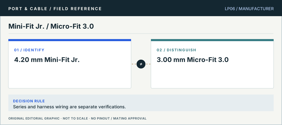
Contrast: 4.20 mm Mini-Fit Jr. compared with 3.00 mm Micro-Fit 3.0. Series and harness wiring are separate verifications. No pinout or scale.
Mini-Fit Jr. / Micro-Fit 3.0Series and harness wiring are separate verifications. Original editorial logic plate, not verified mating geometry or a physical pinout.
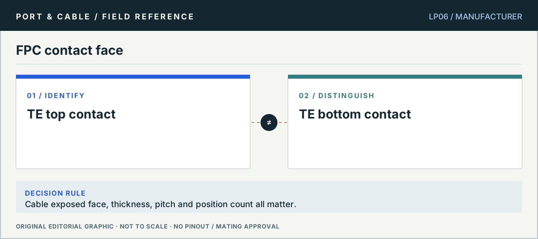
Contrast: TE top contact compared with TE bottom contact. Cable exposed face, thickness, pitch and position count all matter. No pinout or scale.
FPC contact faceCable exposed face, thickness, pitch and position count all matter. Original editorial logic plate, not verified mating geometry or a physical pinout.
03 / TASK NOTES

Questions you can answer before buying a cable

Direct answers, consequences of getting it wrong, exact next checks and links to the registered canonical evidence.

01 / P358

Mini-Fit Jr. is not Micro-Fit 3.0

Is Mini-Fit Jr. the same as Micro-Fit 3.0?

ANSWER FIRST

No. Molex lists separate 4.20 mm Mini-Fit Jr. and 3.00 mm Micro-Fit 3.0 families. Each has its own mating components. Do not assume a PC power harness is compatible because the overall housing looks similar.

Three checks before deciding

  1. Read the full housing and terminal code.
  2. Match both sides in the exact Molex series documents.
  3. Check device wiring and the PSU’s own cable requirements independently.
Canonical reference: Molex Mini-Fit Jr. connector family ↗
Open the original claim and source trail (3 claims)

Only the narrow canonical source claims listed below are registered evidence. The cautionary next checks are educational method, not a field safety approval.

  1. C358A — Molex product 874272002 is described as a Mini-Fit Jr. right-angle PCB header with 20 circuits and 4.20 mm nominal pitch.
  2. C358B — The cited Molex product is a PCB header example, not a universal pinout, replacement cable or safety endorsement for a power supply.
  3. C358C — Molex 0039012240 is listed as a natural-color receptacle housing with 24 circuits, two rows and 4.20 mm mating pitch; these are housing-level catalogue fields, not an ATX cable-assembly identity.
02 / P358

A Mini-Fit Jr. product is not a harness pinout

What does Molex 874272002 actually identify?

ANSWER FIRST

Molex 874272002 is an example right-angle 20-circuit PCB header with 4.20 mm nominal pitch. That header description does not disclose or approve the wiring of an arbitrary assembled cable.

Three checks before deciding

  1. Identify the header orientation and exact part ID.
  2. Look up the supported mating housing and terminals.
  3. Obtain the equipment-specific wiring diagram before connecting power.
Canonical reference: Molex Mini-Fit Jr. connector family ↗
Open the original claim and source trail (3 claims)

Only the narrow canonical source claims listed below are registered evidence. The cautionary next checks are educational method, not a field safety approval.

  1. C358A — Molex product 874272002 is described as a Mini-Fit Jr. right-angle PCB header with 20 circuits and 4.20 mm nominal pitch.
  2. C358B — The cited Molex product is a PCB header example, not a universal pinout, replacement cable or safety endorsement for a power supply.
  3. C358C — Molex 0039012240 is listed as a natural-color receptacle housing with 24 circuits, two rows and 4.20 mm mating pitch; these are housing-level catalogue fields, not an ATX cable-assembly identity.
03 / P359

A 3.00 mm Micro-Fit header needs its exact mate

What matters besides the Micro-Fit 3.0 pitch?

ANSWER FIRST

Molex product 430451200 is a right-angle dual-row 12-circuit example. Correct row count, mating series, housing, terminals and wiring must be established separately for the actual assembly.

Three checks before deciding

  1. Check the Molex series and product-number suffix.
  2. Confirm keyed features and orientation against the supplier drawing.
  3. Verify the cable-specific circuit assignments and ratings.
Canonical reference: Molex Micro-Fit 3.0 connector family ↗
Open the original claim and source trail (3 claims)

Only the narrow canonical source claims listed below are registered evidence. The cautionary next checks are educational method, not a field safety approval.

  1. C359A — Molex describes product 430451200 as a Micro-Fit 3.0 right-angle header with 3.00 mm nominal pitch, dual-row arrangement and 12 circuits.
  2. C359B — Molex identifies 430451200 as a PCB header; its description does not establish the electrical assignment of a device cable or an intermate with Mini-Fit Jr.
  3. C359C — The manufacturer image for 430451200 depicts a shrouded board header with board-termination tails, not a cable-end housing.
04 / P360

Hirose DF13 versus JST GH

Both are described as 1.25 mm. Do they mate?

ANSWER FIRST

No interchangeability is established. Hirose DF13 and JST GH are separate manufacturers’ families. The 1.25 mm descriptor does not resolve shroud geometry, latch, terminal type or mated part numbers.

Three checks before deciding

  1. Identify the maker’s full code on the PCB or BOM.
  2. Inspect the manufacturer-specific mating matrix.
  3. Verify the position count and electrical assignment without forcing a fit.
Canonical reference: Hirose DF13 miniature crimp connector family ↗
Open the original claim and source trail (3 claims)

Only the narrow canonical source claims listed below are registered evidence. The cautionary next checks are educational method, not a field safety approval.

  1. C360A — Hirose describes its DF13 series as 1.25 mm pitch miniature crimping connectors and lists header, socket and contact product types.
  2. C360B — The DF13 series includes different contact counts and mounting arrangements; a 1.25 mm pitch alone does not specify an exact DF13 part or establish mating to JST GH.
  3. C360C — The Hirose DF13 catalog separately documents single-row and double-row socket families.
05 / P361

Top-contact FPC is a part property

What is the significance of TE 1-2492111-7?

ANSWER FIRST

TE lists this named 0.5 mm, 17-position ZIF part as top-contact. It illustrates why contact side and the exact terminal orientation must be checked; “0.5 mm ribbon” is insufficient.

Three checks before deciding

  1. Find the TE product number.
  2. Check which cable face exposes copper in the required insertion orientation.
  3. Read the drawing for thickness, number of positions and actuator type.
Canonical reference: TE 0.5 mm top-contact FPC ZIF connector — 1-2492111-7 ↗
Open the original claim and source trail (3 claims)

Only the narrow canonical source claims listed below are registered evidence. The cautionary next checks are educational method, not a field safety approval.

  1. C361A — TE Connectivity specifies 1-2492111-7 as a 0.5 mm pitch, 17-position ZIF FPC connector with a top contact mating location and right-angle board orientation.
  2. C361B — The TE product page describes a specific top-contact board connector; the description alone does not endorse a different cable thickness, pitch, position count or bottom-contact insertion.
  3. C361C — TE lists part 1-2492111-7 with a stuffer actuator and a specified mating FPC/FFC thickness of 0.3 mm.
06 / P362

Bottom contact is not the same ZIF variant

What distinguishes TE 1-2492104-0?

ANSWER FIRST

TE describes this 0.5 mm, ten-position right-angle ZIF board part as bottom-contact. It differs from the cited top-contact 17-position example in more than contact orientation.

Three checks before deciding

  1. Read the complete product part number.
  2. Check conductor face and the connector’s insertion/latch geometry.
  3. Confirm position count, cable thickness and device pin functions.
Canonical reference: TE 0.5 mm bottom-contact FPC ZIF connector — 1-2492104-0 ↗
Open the original claim and source trail (3 claims)

Only the narrow canonical source claims listed below are registered evidence. The cautionary next checks are educational method, not a field safety approval.

  1. C362A — TE Connectivity specifies 1-2492104-0 as a 0.5 mm pitch, 10-position ZIF FPC connector with a bottom-contact mating location and right-angle board orientation.
  2. C362B — The TE bottom-contact part is a separate product identity from the top-contact example; identical nominal pitch alone does not prove a compatible FPC or cable insertion orientation.
  3. C362C — TE lists part 1-2492104-0 with a stuffer actuator and a specified mating FPC/FFC thickness of 0.3 mm.