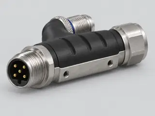
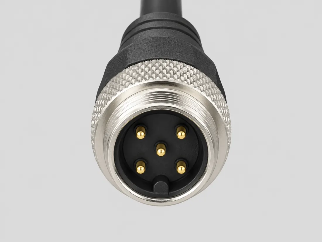
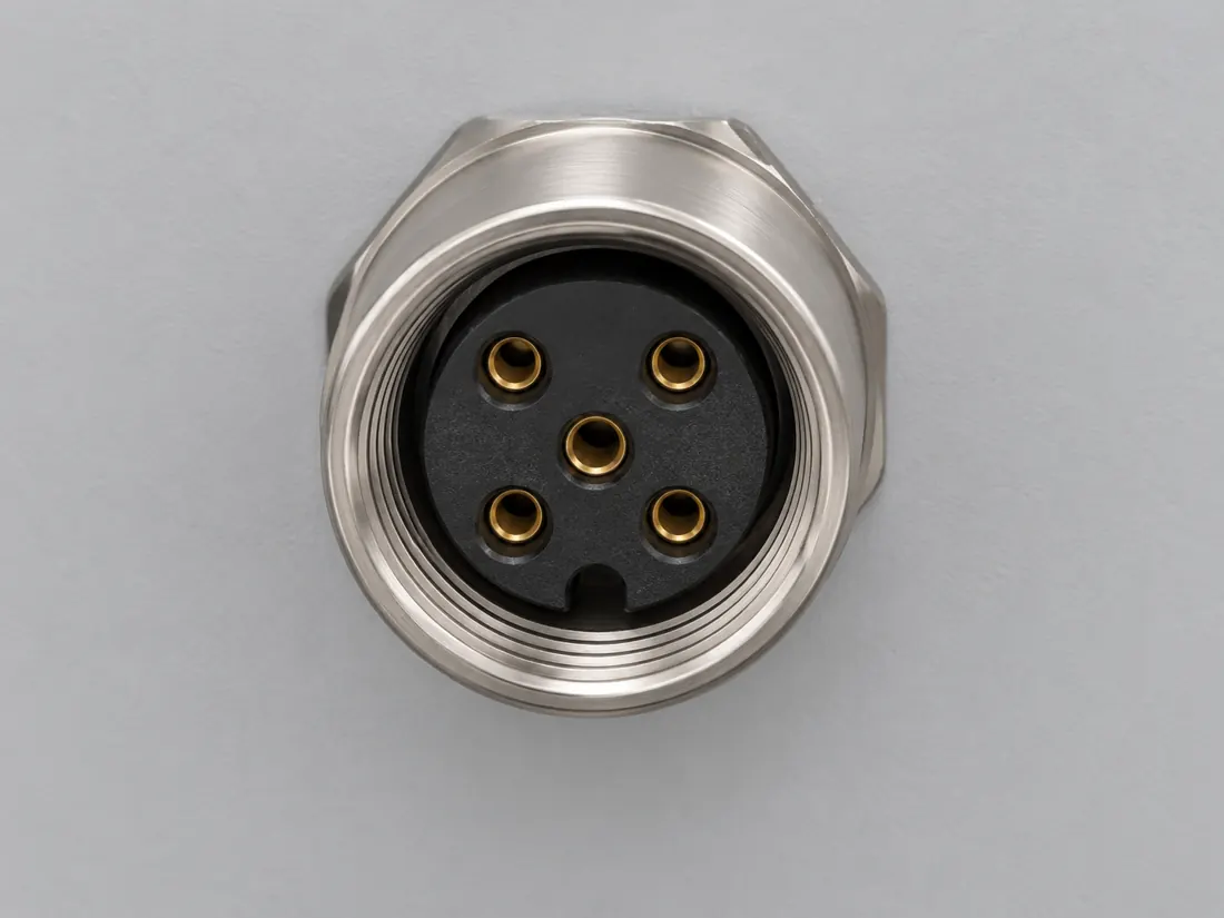
Three-quarter view Computer-generated illustration with prior AI visual review. Not a photograph, measurement or compatibility check. Independent technical and rights review pending.
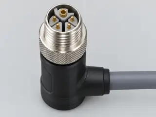
Mating face Computer-generated illustration with prior AI visual review. Not a photograph, measurement or compatibility check. Independent technical and rights review pending.
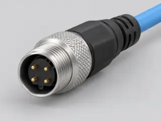
Fitted in place Computer-generated illustration with prior AI visual review. Not a photograph, measurement or compatibility check. Independent technical and rights review pending.
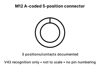
Recognition drawing Original schematic, not to scale. Drawing review pending.
Image inspection / P251
See the view. Check its scope.
1 registered view for this reference. Different part examples are not automatically mates; all remain not to scale and independently unapproved.
(private workspace)
P251 / Source-observed physical study
Phoenix Contact 1836717
Phoenix Contact 1836717
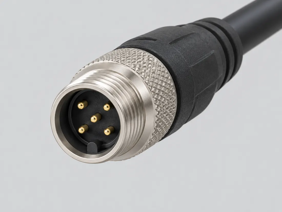
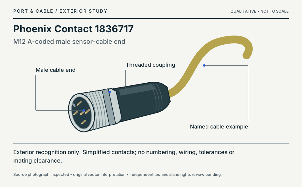
Oblique exterior, connection end at left; simplified contact features · Cable plug / cable end
Not to scale. Technical and rights review pending.
Inspect view & provenance ↗ (private workspace)
Network notes / Industrial / P251
Can cable color distinguish an A-coded sensor cable?
FIELD NOTES 05
Not reliably. Phoenix Contact lists 1836717 as an unshielded five-position A-coded sensor/actuator cable and offers several grip-body colors. The pictured yellow cable is a named example, not a color key for all M12 products.
Identify first
Read the part and the device.
Read A coding, five-position designation and male/female end roles. The outer thread and jacket color do not establish signal assignments.
Still unresolved
Keep this requirement open.
Unknown sensor wiring, Ethernet operation, power supply requirements and a compatible mating part are not resolved by the exterior study.
Explicit source exclusion · named example only
Is one grip color a unique identifier for cable 1836717?
No; the configurable product listing offers multiple grip-body colors.
Boundary. This rejects a color-only identification, not the documented A-coded designation.
Next check. Read the complete configuration and connector designation.
C251C (private workspace) — Phoenix Contact 1836717 is a configurable unshielded five-position M12 A-coded male-to-female sensor/actuator cable. The listing offers multiple grip-body colors, so the shown color is not a unique coding identifier.
V121 named-product or explicitly scoped manufacturer distinction only; no wiring instruction, independent engineering approval or end-to-end compatibility guarantee.
Source interpretation is not independent engineering review, hardware testing, wiring advice or a public-release approval.
Inspect the named exterior · Phoenix Contact 1836717
Not to scale. Simplified exterior and contact features; no pin numbering, wire assignments, tolerances, mating clearance or manufacturing dimensions. Qualitative exterior; not to scale.
M12 A-coded male sensor-cable end; Oblique exterior, connection end at left; simplified contact features. Manufacturer product photograph 115698 inspected 11 October 2026. Original interpretation of the named exterior; not a measured drawing or a copied photograph.
Original source-scoped paraphrase and qualitative vector interpretation; no manufacturer raster artwork republished. Independent technical and rights review remains pending.
The five-position A-coded M12 form is widely encountered in sensor/actuator cabling and is mechanically distinct from other M12 codings. [C251A]
Phoenix Contact 1836717 is a configurable unshielded five-position M12 A-coded male-to-female sensor/actuator cable. The listing offers multiple grip-body colors, so the shown color is not a unique coding identifier. [C251C]
HARTING describes A-coded circular connectors mainly in sensor/actuator signal and field-device power applications, whereas D-coded M12 is an industrial Ethernet form. A five-position A-coded product is not interchangeable solely because both have an M12 outer thread. [C251D]
Source-scoped identification facts
Each value retains its exact example, role and measurement axis. Facts from different parts must not be combined into an invented component.
Documented examples; not a mating drawing or compatibility approval
5 (Claim C251A); 5 (Claim C251B); 5 (Claim C251C); 5 (Claim C251D); 5 (Phoenix Contact 1836717 / connection 1); 5 (Phoenix Contact 1836717 / connection 2)S271 · S289 · S503 · S647 · S503Source-scoped examples are separate; select the exact variant and measured axis. V43 catalogue-expansion identification fact only; not independent technical approval, fabrication data, wiring instruction, protocol guarantee or end-to-end compatibility proof. V44 contact-designation/orientation reference only; no universal signal assignment, wire color, voltage/current rating or device compatibility is inferred. V121 named-product or explicitly scoped manufacturer distinction only; no wiring instruction, independent engineering approval or end-to-end compatibility guarantee. V178 Coding-class and application distinction only; electrical and mechanical mating of actual parts unverified. Original bounded manufacturer paraphrase; publication and technical review pending. Phoenix Contact 1836717 / connection 1. Named primary-source example only. Identification facts do not certify mating, electrical compatibility, fabrication or powered use. Phoenix Contact 1836717 / connection 2. Named primary-source example only. Identification facts do not certify mating, electrical compatibility, fabrication or powered use.
Connector role
Straight M12 cable plug (Phoenix Contact 1836717 / connection 1); Straight M12 cable socket (Phoenix Contact 1836717 / connection 2)S503Source-scoped examples are separate; select the exact variant and measured axis. Phoenix Contact 1836717 / connection 1. Named primary-source example only. Identification facts do not certify mating, electrical compatibility, fabrication or powered use. Phoenix Contact 1836717 / connection 2. Named primary-source example only. Identification facts do not certify mating, electrical compatibility, fabrication or powered use.
Contact gender / arrangement
male (Phoenix Contact 1836717 / connection 1); female (Phoenix Contact 1836717 / connection 2)S503Source-scoped examples are separate; select the exact variant and measured axis. Phoenix Contact 1836717 / connection 1. Named primary-source example only. Identification facts do not certify mating, electrical compatibility, fabrication or powered use. Phoenix Contact 1836717 / connection 2. Named primary-source example only. Identification facts do not certify mating, electrical compatibility, fabrication or powered use.
Mounting
cable (Phoenix Contact 1836717 / connection 1); cable (Phoenix Contact 1836717 / connection 2)S503Source-scoped examples are separate; select the exact variant and measured axis. Phoenix Contact 1836717 / connection 1. Named primary-source example only. Identification facts do not certify mating, electrical compatibility, fabrication or powered use. Phoenix Contact 1836717 / connection 2. Named primary-source example only. Identification facts do not certify mating, electrical compatibility, fabrication or powered use.
Keying / polarization
A coding (Phoenix Contact 1836717 / connection 1); A coding (Phoenix Contact 1836717 / connection 2)S503Source-scoped examples are separate; select the exact variant and measured axis. Phoenix Contact 1836717 / connection 1. Named primary-source example only. Identification facts do not certify mating, electrical compatibility, fabrication or powered use. Phoenix Contact 1836717 / connection 2. Named primary-source example only. Identification facts do not certify mating, electrical compatibility, fabrication or powered use.
Manufacturer
Phoenix Contact (Phoenix Contact 1836717 / connection 1); Phoenix Contact (Phoenix Contact 1836717 / connection 2)S503Source-scoped examples are separate; select the exact variant and measured axis. Phoenix Contact 1836717 / connection 1. Named primary-source example only. Identification facts do not certify mating, electrical compatibility, fabrication or powered use. Phoenix Contact 1836717 / connection 2. Named primary-source example only. Identification facts do not certify mating, electrical compatibility, fabrication or powered use.
Exact part / implementation
Phoenix Contact 1836717 / connection 1 (Phoenix Contact 1836717 / connection 1); Phoenix Contact 1836717 / connection 2 (Phoenix Contact 1836717 / connection 2)S503Source-scoped examples are separate; select the exact variant and measured axis. Phoenix Contact 1836717 / connection 1. Named primary-source example only. Identification facts do not certify mating, electrical compatibility, fabrication or powered use. Phoenix Contact 1836717 / connection 2. Named primary-source example only. Identification facts do not certify mating, electrical compatibility, fabrication or powered use.
Not recorded: Populated contacts, Contact rows, Contact pitch, Dimensions / axis, Coupling / latch, Shell / form, Series, Recorded markings, View convention. Unknown fields stay unknown; illustrations supply no measurements or pin assignments.
Recorded variant and source limits
A-coding and contact numbering do not establish a universal sensor/actuator protocol, wire color or electrical rating.
No fabrication dimensions or mating tolerances are published in this profile.
Not included. Check exact device and accessory documentation.
A boundary, not an omission to guess around.
Use the source-backed form or position count only for identification. Resolve ratings, protocol, direction, wiring, cable construction and exact device support from the relevant equipment and component documentation.
Before you connect
What to check
Identify the exact connector family and variant from the equipment or cable documentation.
Keep shape, contact count, protocol, electrical rating and device support as separate facts.
Do not force, rewire or adapt a connector from this recognition record; resolve the remaining requirements first.
Choose the exact wiring. Pin numbers follow its stated view; a schematic does not establish physical positions. Check your exact device before wiring.
What the status labels mean
Confirmed
Recorded research passes agree within this variant; this is not independent human review or hardware validation.
Single source
Only one underlying document, or one pass, supports this assignment.
Device-specific
Supported for the named equipment or wiring only. Check your device’s manual.
Unverified
Missing or conflicting evidence. Do not wire from this row.
Not connected
The source explicitly says NC, no contact or no pin for this wiring.
What is not established
This field note does not approve a connection, adapter, cable assembly, rewiring scheme or fabricated part. It intentionally omits unsupported pin assignments and mechanical tolerances.
AI-assisted inspection is not independent engineering review. Source scope and access limitations are disclosed below. Procedural checklists are editorial requirements, not hardware measurements.
Locator: Product properties Access: public page. Identification/reference scope only. V43 does not convert this source into a universal pinout, fabrication drawing, electrical approval, protocol guarantee or end-to-end compatibility verdict.
Phoenix Contact 1836717 is a configurable unshielded five-position M12 A-coded male-to-female sensor/actuator cable. The listing offers multiple grip-body colors, so the shown color is not a unique coding identifier.
Locator: Product description; product properties; grip-body color choices; connector ends; photograph 115698 Access: public page. Named five-position A-coded unshielded cable example. Photograph colors are not a coding or protocol standard. No raw HTML or manufacturer image archive is represented as retained.
Claim scope: V121 named-product or explicitly scoped manufacturer distinction only; no wiring instruction, independent engineering approval or end-to-end compatibility guarantee.. Next review due 2027-01-09.
HARTING describes A-coded circular connectors mainly in sensor/actuator signal and field-device power applications, whereas D-coded M12 is an industrial Ethernet form. A five-position A-coded product is not interchangeable solely because both have an M12 outer thread.
Locator: Circular coding: A-coded, D-coded, K-coded, S-coded, X-coded, Y-coded sections Access: public page. Visible manufacturer facts are source-scoped and may change; confirm the exact component/revision and documented applicability; no independent technical certification is claimed.
Claim scope: V178 Coding-class and application distinction only; electrical and mechanical mating of actual parts unverified. Original bounded manufacturer paraphrase; publication and technical review pending.. Next review due 2027-01-13.
Assessment 2026-10-22 · earliest scheduled source review 2027-01-04. This is a recorded-date assessment, not a live source check. Page-level independent review is not established by this panel.
Scoped support: Identifies five-position M12 plug/socket connectors with A-coding in a sensor/actuator cable.
Not established / limitations: Identification/reference scope only. V43 does not convert this source into a universal pinout, fabrication drawing, electrical approval, protocol guarantee or end-to-end compatibility verdict.
Scoped support: Named five-position A-coded unshielded cable example. Photograph colors are not a coding or protocol standard.
Not established / limitations: Named five-position A-coded unshielded cable example. Photograph colors are not a coding or protocol standard. No raw HTML or manufacturer image archive is represented as retained.
HARTING Technology Group · Unclassified publisher domain · inspected 2026-10-15 · due 2027-01-13
Within inspection window
Scoped support: Manufacturer-authored class-level application/coding comparisons; not exact mating, terminal assignments or power ratings for arbitrary parts
Not established / limitations: Visible manufacturer facts are source-scoped and may change; confirm the exact component/revision and documented applicability; no independent technical certification is claimed.
Phoenix Contact 1836717 is a configurable unshielded five-position M12 A-coded male-to-female sensor/actuator cable. The listing offers multiple grip-body colors, so the shown color is not a unique coding identifier.
Claim scope: V121 named-product or explicitly scoped manufacturer distinction only; no wiring instruction, independent engineering approval or end-to-end compatibility guarantee.
HARTING describes A-coded circular connectors mainly in sensor/actuator signal and field-device power applications, whereas D-coded M12 is an industrial Ethernet form. A five-position A-coded product is not interchangeable solely because both have an M12 outer thread.
Claim scope: V178 Coding-class and application distinction only; electrical and mechanical mating of actual parts unverified. Original bounded manufacturer paraphrase; publication and technical review pending.
Recorded evidence only. An inspection date, publisher label, source link or generated packet is not independent technical review, hardware testing, fabrication approval or a compatibility verdict.
Industrial coding field check · M12 A · sensor
Can I use M12 A-coded sensor cabling for D-coded Ethernet?
Short answer Do not assume so. A-coded sensor/actuator connectors have a different coding and intended application from D-coded Ethernet.
Verify next
Identify A or D coding on the exact port and cable; verify the control-system wiring before any connection.
Not yet established
Neither matching outer thread nor the same nominal contact count establishes an approved mate.
Show source-checked observations (not independently approved)
C251D — HARTING describes A-coded circular connectors mainly in sensor/actuator signal and field-device power applications, whereas D-coded M12 is an industrial Ethernet form. A five-position A-coded product is not interchangeable solely because both have an M12 outer thread. S647 · HARTING Technology Group
Symbolic reference, not connector gauging, manufacturing dimensions, wiring, approved mating, hardware test or publication approval.

 (private workspace)