FIELD GUIDESource-led reference

P194 / Storage / Connector

SATA 15-pin power connector

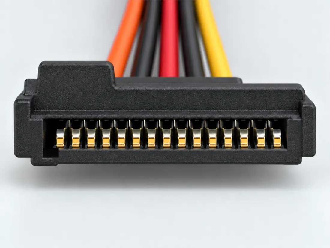
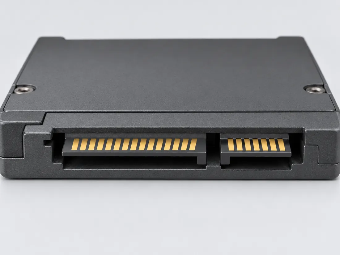
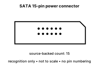
Serial ATA includes a distinct 15-position power connector alongside the separate 7-pin data connector.

Also called SATA power 15 pin SATA power Serial ATA power

SATA data and SATA power are separate interfaces even when combined in one drive-side assembly.

Look for

Count the wider power section separately from the seven-position data section and read the drive/backplane documentation.

Claim inspection dates: 2026-10-05, 2026-10-13 · Independent review pending

Field answer / P194 · Source-checked, human review pending

Which SATA connector supplies power, and which carries data?

First answerSerial ATA includes a distinct 15-position power connector alongside the separate 7-pin data connector.

Next observation: Identify the power source and the exact drive-side connector before considering any PSU lead or adapter.

Original qualitative identification schematic for SATA 15-pin power connector; not a precision mating or wiring drawing
Original V36 recognition schematic; not to scale. Contact marks are illustrative and unnumbered unless the caption states only a source-backed position count; not a wiring, gauging or manufacturing drawing.

What this does not establish

The 15-position SATA power form is different from the seven-contact data form and from older peripheral power connectors. Matching the shell does not establish voltage rails, wiring, a PSU rating or safe adaptation.

Verify before choosing a cable or part

  1. Identify the exact connector family and variant from the equipment or cable documentation.
  2. Keep shape, contact count, protocol, electrical rating and device support as separate facts.
  3. Do not force, rewire or adapt a connector from this recognition record; resolve the remaining requirements first.
Inspect the 3 inherited evidence claims and source limits

These are the existing, individually scoped observations—not fresh source inspections, a universal pinout, approved geometry or a device-specific compatibility verdict.

  1. C194A / canonical evidence anchor — Molex identifies Serial ATA power and signal connector families; the drive-side power section is the 15-position SATA power form.

    V36 catalogue-expansion identification fact only; not independent technical approval, fabrication data, wiring instruction or end-to-end compatibility proof. · source checked; independent sign-off pending.

  2. C194B / canonical evidence anchor — Intel ATX 336521 version 2.01 separately documents required Serial ATA power-supply connectors within its dated PSU design-guide scope; a SATA power connection must not be identified by a 7-position data-only lead.

    V140 / Source-scoped historical or exact-part identity only. No wiring, pinout, universal fit, cable/terminal assembly, device rating, fabrication or publication approval. · source checked; independent sign-off pending.

  3. C194C / canonical evidence anchor — An ATX-era peripheral four-contact housing and a SATA 15-position power connector are documented as different identity families by the same historical design guide; similar PSU origin does not make their termination or mating compatible.

    V140 / Source-scoped historical or exact-part identity only. No wiring, pinout, universal fit, cable/terminal assembly, device rating, fabrication or publication approval. · source checked; independent sign-off pending.

Shape, plug/socket view, contact roles and exact model capability must be checked separately. Review source authority and publication status ↓

Image inspection / P194

See the view. Check its scope.

1 registered view for this reference. Different part examples are not automatically mates; all remain not to scale and independently unapproved.

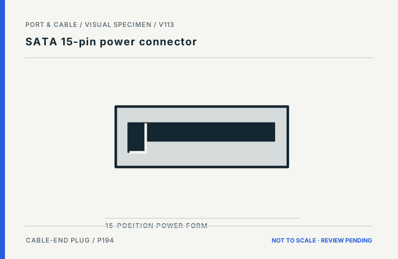
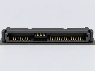
SATA 15-pin power connector: Wider fifteen-position power family. Drive-facing female cable-plug opening concept; qualitative L-shaped key. Qualitative source-linked recognition study, not a pinout or a dimensional guide. (private workspace)

P194 / Inherited recognition study

SATA 15-pin power connector

SATA 15-pin power connector

Drive-facing female cable-plug opening concept; qualitative L-shaped key · Cable plug / cable end

Not to scale. Technical and rights review pending.

Inspect view & provenance (private workspace)
INTERNAL SYSTEMS / DRIVES

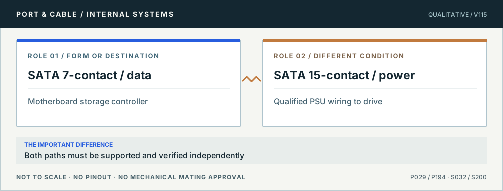
SATA power is not a second data interface

A Molex family overview identifies the separate SATA power contacts distinct from the signal interface. A drive’s power wiring must match the exact device and power supply. Generic molded adapters, repinning or an unknown modular-PSU cable are not established safe by the L-shaped plug housing.

Conceptual role comparison: SATA 7-contact / data versus SATA 15-contact / power. Both paths must be supported and verified independently. Not to scale, no pinout or mechanical mating dimensions.
SATA uses two distinct paths. Original qualitative role diagram; not mechanical artwork, not to scale or a wiring map. Source context S032 · S200.

Three checks before proceeding

  1. Read the drive label and the PSU’s approved drive-power harness documentation.
  2. Do not repin or improvise voltage converters; avoid unknown adapters.
  3. Confirm the SATA data and host path separately from drive power.

One mistake to avoid

Assuming a SATA-looking adapter guarantees correct supply rails, quality or power budget.

Full technical reading, sources and related identities →

Claim-specific evidence remains in the canonical record. Concept diagrams do not show any safe wiring or mechanical mating geometry.

Signal-path fieldbook

Before a cable or module is ordered.

Read the answer, keep mechanical fit separate from the signal path, and verify the named endpoint. These editorial studies reuse inherited source records; no compatibility has been laboratory confirmed.

V106N05 / host storageDevice qualification required

A SATA data plug is connected, but the drive stays off. Does that cable supply power?

Field answerDo not treat a seven-contact SATA data cable as a power lead. The source-backed SATA system distinguishes the seven-contact signal connector from the separate 15-position SATA power form. Drive power and the host data connection are independent requirements.

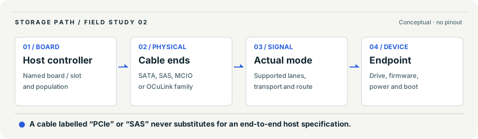
Conceptual storage path: host board and controller, exact connector or cable ends, transport support, and storage endpoint must each be checked independently.
Interpretation study, not a wiring or mating diagram. In order: Identify the board/controller and the specific socket label. / Trace the documented cable ends and the intended interface or lanes. / Confirm the device, power and mode; physical fit is not qualification. This is not evidence of a working connection.

Four checks that must stay separate

Evidence layerWhat is established or still conditional
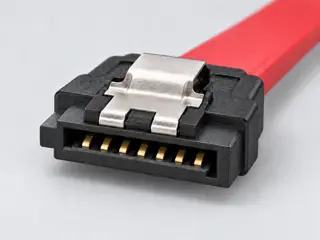
Data connectionStarTech’s SATA18 example specifies seven-contact SATA data connections; the plug is not a power supply.
Drive-side powerMolex distinguishes signal and power forms within the Serial ATA connector system; the inherited power reference is 15 positions.
Endpoint requirementsThe drive, host controller, enclosure and approved PSU connection must be checked separately before any power or troubleshooting action.
Manufacturer scopeS032 concerns StarTech SATA18 data cable; S200 is a Molex SATA/SAS family overview, not a universal power harness drawing.

Check next, in this order

  1. Identify the drive and whether it uses a separate SATA power connection or a proprietary enclosure/backplane.
  2. Follow the exact computer or enclosure manufacturer’s approved power-off, cabling and PSU instructions.
  3. Only after the documented data and power paths are established, check host controller recognition and storage settings.

Not yet established These catalogue records do not specify the user’s voltage rails, pin wiring, adapters, PSU capacity, hot-plug procedure or drive health. Do not improvise a powered cable.

Read the claim and manufacturer source boundaries

Existing scoped claims: C029A (Consumer identification / documented standard or product class only); C194A (V36 catalogue-expansion identification fact only; not independent technical approval, fabrication data, wiring instruction or end-to-end compatibility proof.). No newly authored empirical specifications; manufacturer catalogue claims remain conditional on the actual part and host.

  • S032 · StarTech.comPDF p. 1: two seven-contact data receptacles; p. 3: Connector(s) table, visually inspected.; inherited review 2026-10-07. Exact SATA18 product description only. Seven-contact data receptacles do not establish separate SATA power wiring. No universal rate, length, dimensional or mating guarantee is adopted.
  • S200 · MolexProduct-family overview; inherited review 2026-10-05. Identification/reference scope only. V36 does not convert this source into a universal pinout, fabrication drawing, electrical approval or end-to-end compatibility verdict.

Existing inspection dates remain unchanged. This editorial synthesis is not a physical mating test, pinout, optical budget, manufacturer device approval or deployment authorization.

Visual atlas / P194 / 2026

Recognize the right physical clue.

FIGURE · REVIEW PENDING
SATA 15-pin power connector: Wider fifteen-position power family. Drive-facing female cable-plug opening concept; qualitative L-shaped key. Qualitative source-linked recognition study, not a pinout or a dimensional guide.
Cable-end plug. Drive-facing female cable-plug opening concept; qualitative L-shaped key.

What to look for

Wider fifteen-position power family

What the drawing does not prove

Positions are named, not drawn as electrical contacts; sizes and key tolerances are unmeasured.

Both are separately keyed connectors. Confirm drive, cable and power-supply implementation before assembly.

No fabrication dimensions, conductor routing, guaranteed fit or device approval. For electrical, power and optical interfaces, follow the original equipment instructions.

Figure evidence, orientation & usage rights

Uses previously recorded V112 manufacturer claim/source inspections; October 2026 supplementary public-source spot checks are documented separately, not treated as a refreshed approval.

Original Port & Cable interpretive vector, no third-party photo, copied CAD, logo or vendor drawing. Third-party product photos, logos and source drawings are not redistributed. No independent technical or rights certification is claimed.

Original claim identifiers: C194A (private workspace). Legacy evidence dates and rights assessments remain as recorded.

The useful distinction

Recognize it. Then verify it.

Serial ATA includes a distinct 15-position power connector alongside the separate 7-pin data connector. [C194A]

Intel ATX 336521 version 2.01 separately documents required Serial ATA power-supply connectors within its dated PSU design-guide scope; a SATA power connection must not be identified by a 7-position data-only lead. [C194B]

An ATX-era peripheral four-contact housing and a SATA 15-position power connector are documented as different identity families by the same historical design guide; similar PSU origin does not make their termination or mating compatible. [C194C]

Source-scoped identification facts

Each value retains its exact example, role and measurement axis. Facts from different parts must not be combined into an invented component.

Documented examples; not a mating drawing or compatibility approval
Nominal contacts15S200Position count is an identification aid; V36 does not publish the electrical assignment.
Positions / cavity span15 (Claim C194A); 7 (Claim C194B); 15 (Claim C194C)S200 · S583 · S577 · S583Recorded source-scoped values; named examples do not describe every family variant or establish compatibility. V36 catalogue-expansion identification fact only; not independent technical approval, fabrication data, wiring instruction or end-to-end compatibility proof. V140 / Source-scoped historical or exact-part identity only. No wiring, pinout, universal fit, cable/terminal assembly, device rating, fabrication or publication approval.
Contact rows1 (675820000)S910Named source examples retain separate role, part, view and axis limits; values are not a universal family specification. 675820000. Documented role: socket. 15positions maximum and5terminal sets per housing. Unloaded housing is not a measured15-contact specimen.; Molex labels limited information; do not replace explicit keying/polarization distinctions with a generic L-key statement.
Contact pitch1.27 mm mating interface (675820000)S910Named source examples retain separate role, part, view and axis limits; values are not a universal family specification. 675820000. Documented role: socket. 15positions maximum and5terminal sets per housing. Unloaded housing is not a measured15-contact specimen.; Molex labels limited information; do not replace explicit keying/polarization distinctions with a generic L-key statement.
Connector rolesocket (675820000)S910Named source examples retain separate role, part, view and axis limits; values are not a universal family specification. 675820000. Documented role: socket. 15positions maximum and5terminal sets per housing. Unloaded housing is not a measured15-contact specimen.; Molex labels limited information; do not replace explicit keying/polarization distinctions with a generic L-key statement.
Keying / polarizationKeying to mating part:yes; mating lock:no; polarized-to-mating:no per catalog (675820000)S910Named source examples retain separate role, part, view and axis limits; values are not a universal family specification. 675820000. Documented role: socket. 15positions maximum and5terminal sets per housing. Unloaded housing is not a measured15-contact specimen.; Molex labels limited information; do not replace explicit keying/polarization distinctions with a generic L-key statement.
ManufacturerMolex (675820000)S910Named source examples retain separate role, part, view and axis limits; values are not a universal family specification. 675820000. Documented role: socket. 15positions maximum and5terminal sets per housing. Unloaded housing is not a measured15-contact specimen.; Molex labels limited information; do not replace explicit keying/polarization distinctions with a generic L-key statement.
Series67582 (675820000)S910Named source examples retain separate role, part, view and axis limits; values are not a universal family specification. 675820000. Documented role: socket. 15positions maximum and5terminal sets per housing. Unloaded housing is not a measured15-contact specimen.; Molex labels limited information; do not replace explicit keying/polarization distinctions with a generic L-key statement.
Exact part / implementation675820000 (675820000)S910Named source examples retain separate role, part, view and axis limits; values are not a universal family specification. 675820000. Documented role: socket. 15positions maximum and5terminal sets per housing. Unloaded housing is not a measured15-contact specimen.; Molex labels limited information; do not replace explicit keying/polarization distinctions with a generic L-key statement.

Not recorded: Populated contacts, Dimensions / axis, Contact gender / arrangement, Mounting, Coupling / latch, Shell / form, Recorded markings, View convention. Unknown fields stay unknown; illustrations supply no measurements or pin assignments.

Recorded variant and source limits
  • Check the exact device manual before wiring or applying power.
  • Seagate Laptop SSHD SATA legacy connector table: Table 8 device-plug power segment. Physical mating-face left/right is not established by this table.
  • SATA Revision 3.0 device power segment: Device-plug P1-P15; Figure 30 on p. 83 marks pin P1 and the connector keys.
  • Seagate Exos Xz ST32000NM001F / ST30000NM011F device power: Named drive device-plug P1-P15; Table 5 provides electrical identity, not a mating-face left/right drawing.
Report a correction to these facts →

Bounded facts, visible unknowns

Specifications and limits

SATA 15-pin power connector facts and limitations
Documented identification15-position Serial ATA power connector form. [C194A]
Mechanical dimensionsNo independently reviewed mechanical drawing in V36; do not use this page for fabrication, fit testing or tolerance work.
Engineering pinoutSource-checked engineering profile available; independent review pending. Open engineering profile →
Verified device listNot included. Check exact device and accessory documentation.
A boundary, not an omission to guess around.

Use the source-backed form or position count only for identification. Resolve ratings, protocol, direction, wiring, cable construction and exact device support from the relevant equipment and component documentation.

Before you connect

What to check

  1. Identify the exact connector family and variant from the equipment or cable documentation.
  2. Keep shape, contact count, protocol, electrical rating and device support as separate facts.
  3. Do not force, rewire or adapt a connector from this recognition record; resolve the remaining requirements first.
Trace a supported connection class →

Pins & wiring

Pinout

Choose the exact wiring. Pin numbers follow its stated view; a schematic does not establish physical positions. Check your exact device before wiring.

What the status labels mean
Confirmed
Recorded research passes agree within this variant; this is not independent human review or hardware validation.
Single source
Only one underlying document, or one pass, supports this assignment.
Device-specific
Supported for the named equipment or wiring only. Check your device’s manual.
Unverified
Missing or conflicting evidence. Do not wire from this row.
Not connected
The source explicitly says NC, no contact or no pin for this wiring.
Wiring variant

Seagate Laptop SSHD SATA legacy connector table

Device-specific wiring. Check your device’s manual before connecting or applying power.

View and evidence limits

Table 8 device-plug power segment. Physical mating-face left/right is not established by this table.

  • P194 SATA 15-pin power — **Agree** on legacy rail positions; **P3/P11 are variant-dependent** — A: Seagate Laptop SSHD. B: SATA 3.0 Gold and Seagate Exos Xz. Legacy P3 is 3.3 V/pre-charge; the named Exos P3 is PWRDIS. P11 activity/staggered-spin-up or grounded behavior remains source/device-specific. B notes unused Exos rails without converting "not used" to an internal NC. Different Seagate manuals plus a separate standards document.
  • This legacy table assigns P3 to 3.3 V. PWDIS/DEVSLP variants and unsupported rails in other drives are not established by this source.
SATA 15-pin power connector engineering referenceTable 8 device-plug power segment. Physical mating-face left/right is not established by this table.SCHEMATIC · physical positions unconfirmedNot to scale · check the named wiring and device manualP1: V33 (device_specific)P1P2: V33 (device_specific)P2P3: V33 (device_specific)P3P4: Ground (device_specific)P4P5: Ground (device_specific)P5P6: Ground (device_specific)P6P7: V5 (device_specific)P7P8: V5 (device_specific)P8P9: V5 (device_specific)P9P10: Ground (device_specific)P10P11: Ground or LED signal (device_specific)P11P12: Ground (device_specific)P12P13: V12 (device_specific)P13P14: V12 (device_specific)P14P15: V12 (device_specific)P15powergrounddataConfigshieldNCUnknown
Schematic only · physical contact positions unconfirmed. Original drawing · not to scale. Scroll sideways if needed.
Seagate Laptop SSHD SATA legacy connector table — source-scoped contact map
PinSignalWhat it doesStatus
P1V33Power connection (V33). Check the specified supply.Device-specific
Sources
P2V33Power connection (V33). Check the specified supply.Device-specific
Sources
P3V33Power connection (V33). Check the specified supply.Device-specific
Sources
P4GroundGround reference and return.Device-specific
Sources
P5GroundGround reference and return.Device-specific
Sources
P6GroundGround reference and return.Device-specific
Sources
P7V5Power connection (V5). Check the specified supply.Device-specific
Sources
P8V5Power connection (V5). Check the specified supply.Device-specific
Sources
P9V5Power connection (V5). Check the specified supply.Device-specific
Sources
P10GroundGround reference and return.Device-specific
Sources
P11Ground or LED signalGround reference and return.Device-specific
Sources
P12GroundGround reference and return.Device-specific
Sources
P13V12Power connection (V12). Check the specified supply.Device-specific
Sources
P14V12Power connection (V12). Check the specified supply.Device-specific
Sources
P15V12Power connection (V12). Check the specified supply.Device-specific
Sources
Sources (1)

SATA Revision 3.0 device power segment

View and evidence limits

Device-plug P1-P15; Figure 30 on p. 83 marks pin P1 and the connector keys.

  • P194 SATA 15-pin power — **Agree** on legacy rail positions; **P3/P11 are variant-dependent** — A: Seagate Laptop SSHD. B: SATA 3.0 Gold and Seagate Exos Xz. Legacy P3 is 3.3 V/pre-charge; the named Exos P3 is PWRDIS. P11 activity/staggered-spin-up or grounded behavior remains source/device-specific. B notes unused Exos rails without converting "not used" to an internal NC. Different Seagate manuals plus a separate standards document.
  • The 2009 standard variant assigns P3 to 3.3 V pre-charge; the named 2024 Seagate variant uses optional PWRDIS. These variants must not be combined or applied solely from the connector shape.
SATA 15-pin power connector engineering referenceDevice-plug P1-P15; Figure 30 on p. 83 marks pin P1 and the connector keys.SCHEMATIC · physical positions unconfirmedNot to scale · check the named wiring and device manualP1: V33 (single_source)P1P2: V33 (single_source)P2P3: V33 (single_source)P3P4: GND (single_source)P4P5: GND (single_source)P5P6: GND (single_source)P6P7: V5 (single_source)P7P8: V5 (single_source)P8P9: V5 (single_source)P9P10: GND (single_source)P10P11: DAS/DSS (single_source)P11P12: GND (single_source)P12P13: V12 (single_source)P13P14: V12 (single_source)P14P15: V12 (single_source)P15powergrounddataConfigshieldNCUnknown
Schematic only · physical contact positions unconfirmed. Original drawing · not to scale. Scroll sideways if needed.
SATA Revision 3.0 device power segment — source-scoped contact map
PinSignalWhat it doesStatus
P1V33Power connection (V33). Check the specified supply.Single source
Sources
P2V33Power connection (V33). Check the specified supply.Single source
Sources
P3V33Power connection (V33). Check the specified supply.Single source
Sources
P4GNDGround reference and return.Single source
Sources
P5GNDGround reference and return.Single source
Sources
P6GNDGround reference and return.Single source
Sources
P7V5Power connection (V5). Check the specified supply.Single source
Sources
P8V5Power connection (V5). Check the specified supply.Single source
Sources
P9V5Power connection (V5). Check the specified supply.Single source
Sources
P10GNDGround reference and return.Single source
Sources
P11DAS/DSSControl, detection or configuration connection; check the source and device.Single source
Sources
P12GNDGround reference and return.Single source
Sources
P13V12Power connection (V12). Check the specified supply.Single source
Sources
P14V12Power connection (V12). Check the specified supply.Single source
Sources
P15V12Power connection (V12). Check the specified supply.Single source
Sources
Sources (1)

Seagate Exos Xz ST32000NM001F / ST30000NM011F device power

Device-specific wiring. Check your device’s manual before connecting or applying power.

View and evidence limits

Named drive device-plug P1-P15; Table 5 provides electrical identity, not a mating-face left/right drawing.

  • P194 SATA 15-pin power — **Agree** on legacy rail positions; **P3/P11 are variant-dependent** — A: Seagate Laptop SSHD. B: SATA 3.0 Gold and Seagate Exos Xz. Legacy P3 is 3.3 V/pre-charge; the named Exos P3 is PWRDIS. P11 activity/staggered-spin-up or grounded behavior remains source/device-specific. B notes unused Exos rails without converting "not used" to an internal NC. Different Seagate manuals plus a separate standards document.
  • The 2009 standard variant assigns P3 to 3.3 V pre-charge; the named 2024 Seagate variant uses optional PWRDIS. These variants must not be combined or applied solely from the connector shape.
SATA 15-pin power connector engineering referenceNamed drive device-plug P1-P15; Table 5 provides electrical identity, not a mating-face left/right drawing.SCHEMATIC · physical positions unconfirmedNot to scale · check the named wiring and device manualP1: V33 (not used) (device_specific)P1P2: V33 (not used) (device_specific)P2P3: PWRDIS (device_specific)P3P4: Ground (device_specific)P4P5: Ground (device_specific)P5P6: Ground (device_specific)P6P7: V5 (device_specific)P7P8: V5 (device_specific)P8P9: V5 (device_specific)P9P10: Ground (device_specific)P10P11: Ground or LED signal (device_specific)P11P12: Ground (device_specific)P12P13: V12 (device_specific)P13P14: V12 (device_specific)P14P15: V12 (device_specific)P15powergrounddataConfigshieldNCUnknown
Schematic only · physical contact positions unconfirmed. Original drawing · not to scale. Scroll sideways if needed.
Seagate Exos Xz ST32000NM001F / ST30000NM011F device power — source-scoped contact map
PinSignalWhat it doesStatus
P1V33 (not used)Power connection (V33 (not used)). Check the specified supply.Device-specific
Sources
P2V33 (not used)Power connection (V33 (not used)). Check the specified supply.Device-specific
Sources
P3PWRDISControl, detection or configuration connection; check the source and device.Device-specific
Sources
P4GroundGround reference and return.Device-specific
Sources
P5GroundGround reference and return.Device-specific
Sources
P6GroundGround reference and return.Device-specific
Sources
P7V5Power connection (V5). Check the specified supply.Device-specific
Sources
P8V5Power connection (V5). Check the specified supply.Device-specific
Sources
P9V5Power connection (V5). Check the specified supply.Device-specific
Sources
P10GroundGround reference and return.Device-specific
Sources
P11Ground or LED signalGround reference and return.Device-specific
Sources
P12GroundGround reference and return.Device-specific
Sources
P13V12Power connection (V12). Check the specified supply.Device-specific
Sources
P14V12Power connection (V12). Check the specified supply.Device-specific
Sources
P15V12Power connection (V12). Check the specified supply.Device-specific
Sources
Sources (1)

What is not established

This field note does not approve a connection, adapter, cable assembly, rewiring scheme or fabricated part. It intentionally omits unsupported pin assignments and mechanical tolerances.

Your next step

Move from the form to the requirement.

The source trail

Evidence for this page

AI-assisted inspection is not independent engineering review. Source scope and access limitations are disclosed below. Procedural checklists are editorial requirements, not hardware measurements.

Back to first citation ↑
C194ASource checked · pending review

Molex identifies Serial ATA power and signal connector families; the drive-side power section is the 15-position SATA power form.

Molex · Serial ATA and SAS connector system ↗

Locator: Product-family overview
Access: public page. Identification/reference scope only. V36 does not convert this source into a universal pinout, fabrication drawing, electrical approval or end-to-end compatibility verdict.

S200: full source recordInspect review dependencies → (private workspace)

Claim scope: V36 catalogue-expansion identification fact only; not independent technical approval, fabrication data, wiring instruction or end-to-end compatibility proof.. Next review due 2027-01-03.

Back to first citation ↑
C194BSource checked · pending review

Intel ATX 336521 version 2.01 separately documents required Serial ATA power-supply connectors within its dated PSU design-guide scope; a SATA power connection must not be identified by a 7-position data-only lead.

Intel · Intel 336521 2.01: Serial ATA PSU connector requirement ↗

Locator: ATX Multi Rail 336521 version 2.01, dated 2023-02-01, Serial ATA Connectors - REQUIRED, dated power-supply design guidance.
Access: public page. Source-scoped historical or exact-part identity only. No wiring, pinout, universal fit, cable/terminal assembly, device rating, fabrication or publication approval.

S583: full source recordInspect review dependencies → (private workspace)

Claim scope: V140 / Source-scoped historical or exact-part identity only. No wiring, pinout, universal fit, cable/terminal assembly, device rating, fabrication or publication approval.. Next review due 2027-01-11.

Back to first citation ↑
C194CSource checked · pending review

An ATX-era peripheral four-contact housing and a SATA 15-position power connector are documented as different identity families by the same historical design guide; similar PSU origin does not make their termination or mating compatible.

Intel · Intel 336521 2.01: historic peripheral power connector scope ↗

Locator: ATX Version 3.0 Multi Rail, document 336521 version 2.01 dated 2023-02-01; Peripheral Connectors; names AMP 1-480424-0 or equivalent.
Access: public page. Source-scoped historical or exact-part identity only. No wiring, pinout, universal fit, cable/terminal assembly, device rating, fabrication or publication approval.

S577: full source recordIntel · Intel 336521 2.01: Serial ATA PSU connector requirement ↗

Locator: ATX Multi Rail 336521 version 2.01, dated 2023-02-01, Serial ATA Connectors - REQUIRED, dated power-supply design guidance.
Access: public page. Source-scoped historical or exact-part identity only. No wiring, pinout, universal fit, cable/terminal assembly, device rating, fabrication or publication approval.

S583: full source recordInspect review dependencies → (private workspace)

Claim scope: V140 / Source-scoped historical or exact-part identity only. No wiring, pinout, universal fit, cable/terminal assembly, device rating, fabrication or publication approval.. Next review due 2027-01-11.

Suggest a correction to this field note →
Put this field note to work.

Add to discovery trayRecord an unsaved candidate (private workspace)

Candidate selection does not confirm the identity or capabilities of your physical item.

Use this reference

From identity to the right next question

Evidence behind this page

Scope first. Source second. Approval separate.

3 linked sources · 3 scoped claims · 0 sources with inspection/access flags.

Page scope: catalogue_expansion_v36

Assessment 2026-10-22 · earliest scheduled source review 2027-01-03. This is a recorded-date assessment, not a live source check. Page-level independent review is not established by this panel.

Inspect 3 source scopes, access limits and dates

S200 · Serial ATA and SAS connector system

Molex · Manufacturer / product-owner domain · inspected 2026-10-05 · due 2027-01-03

Within inspection window

Scoped support: Identifies Serial ATA signal/power, combo, Micro SATA, Slimline SATA, SAS and SlimSAS connector families.

Not established / limitations: Identification/reference scope only. V36 does not convert this source into a universal pinout, fabrication drawing, electrical approval or end-to-end compatibility verdict.

Locator: Product-family overview

S577 · Intel 336521 2.01: historic peripheral power connector scope

Intel · Manufacturer / product-owner domain · inspected 2026-10-13 · due 2027-01-11

Within inspection window

Scoped support: Dated ATX guide identifies TE example for legacy peripheral power; this is not universal current PSU-cable approval. Newer-version banner visible.

Not established / limitations: Source-scoped historical or exact-part identity only. No wiring, pinout, universal fit, cable/terminal assembly, device rating, fabrication or publication approval.

Locator: ATX Version 3.0 Multi Rail, document 336521 version 2.01 dated 2023-02-01; Peripheral Connectors; names AMP 1-480424-0 or equivalent.

S583 · Intel 336521 2.01: Serial ATA PSU connector requirement

Intel · Manufacturer / product-owner domain · inspected 2026-10-13 · due 2027-01-11

Within inspection window

Scoped support: Power-supply design-guide context, not an endorsement of SATA device data wiring, mechanical equivalence, or cables unknown by origin.

Not established / limitations: Source-scoped historical or exact-part identity only. No wiring, pinout, universal fit, cable/terminal assembly, device rating, fabrication or publication approval.

Locator: ATX Multi Rail 336521 version 2.01, dated 2023-02-01, Serial ATA Connectors - REQUIRED, dated power-supply design guidance.

Trace 3 claims to their source records

C194A · P194

Molex identifies Serial ATA power and signal connector families; the drive-side power section is the 15-position SATA power form.

Claim scope: V36 catalogue-expansion identification fact only; not independent technical approval, fabrication data, wiring instruction or end-to-end compatibility proof.

Source links: S200 · Evidence trail → (private workspace)

C194B · P194

Intel ATX 336521 version 2.01 separately documents required Serial ATA power-supply connectors within its dated PSU design-guide scope; a SATA power connection must not be identified by a 7-position data-only lead.

Claim scope: V140 / Source-scoped historical or exact-part identity only. No wiring, pinout, universal fit, cable/terminal assembly, device rating, fabrication or publication approval.

Source links: S583 · Evidence trail → (private workspace)

C194C · P194

An ATX-era peripheral four-contact housing and a SATA 15-position power connector are documented as different identity families by the same historical design guide; similar PSU origin does not make their termination or mating compatible.

Claim scope: V140 / Source-scoped historical or exact-part identity only. No wiring, pinout, universal fit, cable/terminal assembly, device rating, fabrication or publication approval.

Source links: S577 · S583 · Evidence trail → (private workspace)

Prepare this page for review → (private workspace)Read the evidence method →

Recorded evidence only. An inspection date, publisher label, source link or generated packet is not independent technical review, hardware testing, fabrication approval or a compatibility verdict.