FIELD GUIDESource-led reference

P062 / Storage / Connector

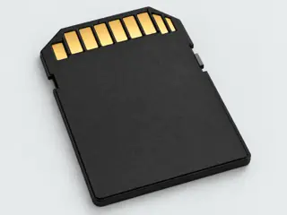
microSD card form

The SD Association treats microSD as a separate, smaller form factor from full-size SD. Capacity, bus interface and speed-class support remain additional distinctions.

Also called micro SD microSD card TF card

Small form factor does not mean a particular speed.

Look for

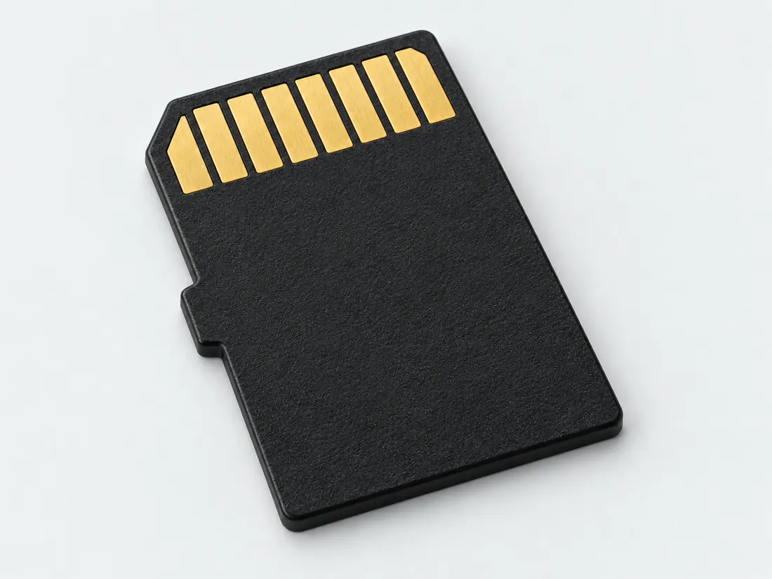
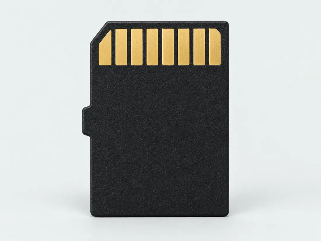
Look for a small keyed memory-card outline. Extra contact rows on some variants matter, so the drawing deliberately does not assign numbered contacts.

Claim inspection dates: 2026-10-01, 2026-10-07 · Independent review pending

Image inspection / P062

See the view. Check its scope.

1 registered view for this reference. Different part examples are not automatically mates; all remain not to scale and independently unapproved.

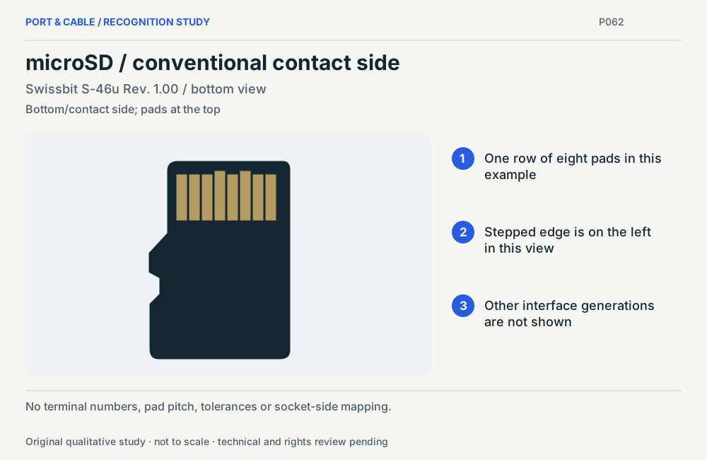
microSD / conventional contact side. One row of eight pads in this example. Stepped edge is on the left in this view. Other interface generations are not shown. No terminal numbers, pad pitch, tolerances or socket-side mapping. Not to scale. (private workspace)

P062 / Source-observed physical study

microSD / conventional contact side

Swissbit S-46u Rev. 1.00 / bottom view

Bottom/contact side; pads at the top · Other declared component

Not to scale. Technical and rights review pending.

Inspect view & provenance (private workspace)
Inspect the illustrationCard-outline schematic · larger view & look-alikes
microSD card form — card-outline schematic; card illustration; original, not-to-scale identification schematic; drawing review pending
View Card-outline schematicDepiction Card illustrationNot to scale · independent drawing review pending

Read the view

Small card outline with stepped left edge

The stepped edge is at the left in this illustration; no slot orientation or numbered contact face is asserted.

About the marks: Contact strokes are symbolic; this is not a full contact-layout drawing.

What it cannot establish: This sketch cannot establish capacity, bus mode, speed class or the presence of extra contact rows.

Enlargement changes display size only. It does not reveal measured geometry, a pin assignment or an approved mating combination.

Compare a likely look-alike

Read the underlying references: S041 · S042. Artwork interpretation remains review-pending.

How to read connector illustrations →

The useful distinction

Recognize it. Then verify it.

The SD Association treats microSD as a separate, smaller form factor from full-size SD. Capacity, bus interface and speed-class support remain additional distinctions. [C062A]

The SD Association lists a nominal microSD envelope of 15 × 11 × 1.0 mm (length × width × thickness). Conventional single-row cards for Default Speed, High Speed and UHS-I use eight contacts. [C062B]

The SD Association overview distinguishes microSD contact counts by interface: High Speed/UHS-I eight, UHS-II sixteen, and one-lane microSD Express sixteen to seventeen. [C062C]

Swissbit S-46u Revision 1.00, page 8, gives this native SD-mode assignment in Figure 2 bottom-view numbering: 1 DAT2, 2 CD/DAT3, 3 CMD, 4 VDD, 5 CLK, 6 VSS, 7 DAT0, 8 DAT1. The same table gives different SPI-mode functions on several pads. [C062D]

The SD Association SD Express Host Implementation Guideline Version 2 (May 2025), section 4.10.2, states that microSD Express needs different connectors because the second-row pad location and size differ from microSD UHS-II. [C062E]

Source-scoped identification facts

Each value retains its exact example, role and measurement axis. Facts from different parts must not be combined into an invented component.

Documented examples; not a mating drawing or compatibility approval
Nominal contacts8S041 · S042 · S041 · S391 · S392Conventional card contact face, not a receptacle terminal or PCB footprint; nominal engineering count, not automatically positions, population or a device wiring map. Conventional card contact face, not a receptacle terminal or PCB footprint
Contact rows1 (Claim C062B)S041 · S042Recorded source-scoped values; named examples do not describe every family variant or establish compatibility. The SD Association lists a nominal microSD envelope of 15 × 11 × 1.0 mm (length × width × thickness). Conventional single-row cards for Default Speed, High Speed and UHS-I use eight contacts. | Nominal microSD card identification and conventional first-row count; no inference about extra contacts, exact host support or fabrication dimensions.
Dimensions / axis15 mm Nominal card length; 11 mm Nominal card width; 1 mm Nominal maximum envelope thicknessS041 · S042Recorded source-scoped values; named examples do not describe every family variant or establish compatibility. nominal_identifier; Conventional card contact face, not a receptacle terminal or PCB footprint
Connector rolesocketS041 · S042 · S041 · S391 · S392Recorded source-scoped values; named examples do not describe every family variant or establish compatibility. Conventional card contact face, not a receptacle terminal or PCB footprint
SeriesmicroSDS919Named source examples retain separate role, part, view and axis limits; values are not a universal family specification. microSD. Nominal dimensions reproduced in the published tuple order; no length/width names invented from unlabelled axes.; Capacity/speed logos are separate standards; no specimen logo, speed or compatibility inferred.

Not recorded: Positions / cavity span, Populated contacts, Contact pitch, Contact gender / arrangement, Mounting, Coupling / latch, Keying / polarization, Shell / form, Manufacturer, Exact part / implementation, Recorded markings, View convention. Unknown fields stay unknown; illustrations supply no measurements or pin assignments.

Recorded variant and source limits
  • Socket pad positions, terminal numbering, tolerances, keep-outs and insertion forces are not established.
  • Capacity-family support, enabled bus mode and speed class require exact card and host documentation.
  • Additional-row contacts are not represented by this conventional first-row contact count.
  • No electrical limits, initialization sequence, wiring procedure or fabrication approval are supplied.
  • SPI-mode roles differ; the displayed native SD functions must not be reused as an SPI wiring table. Extended data-line behavior at startup is not a completed operational design.
  • Transcend USDC10I — sd-native: PDF p.1 Placement contact-side drawing and Pin Definition table. microSD drawing labels 1-8 left to right as printed.
  • Transcend USDC10I — spi: PDF p.1 Placement contact-side drawing and Pin Definition table. microSD drawing labels 1-8 left to right as printed.
  • Transcend USDC10I — Native SD mode: Card contact-side placement drawing on PDF p. 1, contacts toward top; microSD contacts are numbered 1-8 left to right.
  • Transcend USDC10I — SPI mode: Card contact-side placement drawing on PDF p. 1, contacts toward top; microSD contacts are numbered 1-8 left to right.
Report a correction to these facts →

Bounded facts, visible unknowns

Specifications and limits

microSD card form facts and limitations
Record layerPhysical card form [C062A]
Express capabilityRequires explicit card and host documentation [C062A]
Nominal card envelope15 × 11 × 1.0 mm [C062B]
Conventional first-row contacts8; not a universal all-generation count [C062B]
Mechanical dimensionsNominal card envelope is source-checked in the engineering reference. Mechanical tolerances and a fabrication drawing remain unavailable.
Engineering pinoutSource-checked engineering profile available; independent review pending. Open engineering profile →
Verified device listNot included. Check exact device and accessory documentation.
A boundary, not an omission to guess around.

The atlas does not infer SD Express support or a device capacity limit from a visible shape match.

Before you connect

What to check

  1. Confirm that the host takes microSD, not merely another small card.
  2. Record whether the host explicitly requires SD Express.
  3. Check capacity class and recording-class requirements separately.
  4. Use only documented adapter and reader combinations.
Trace a supported connection class →

Pins & wiring

Pinout

Choose the exact wiring. Pin numbers follow its stated view; a schematic does not establish physical positions. Check your exact device before wiring.

What the status labels mean
Confirmed
Recorded research passes agree within this variant; this is not independent human review or hardware validation.
Single source
Only one underlying document, or one pass, supports this assignment.
Device-specific
Supported for the named equipment or wiring only. Check your device’s manual.
Unverified
Missing or conflicting evidence. Do not wire from this row.
Not connected
The source explicitly says NC, no contact or no pin for this wiring.
Wiring variant

Transcend USDC10I — sd-native

Device-specific wiring. Check your device’s manual before connecting or applying power.

View and evidence limits

PDF p.1 Placement contact-side drawing and Pin Definition table. microSD drawing labels 1-8 left to right as printed.

  • P062 microSD — **Agree** on all eight native/SPI positions, but **same source** — Same Transcend USDC10I V1.0 document, URL and hash in both. Reserved SPI 1/8 are not inferred internally disconnected. The two modes and later additional-contact systems remain separate.
  • UHS-II, SD Express/microSD Express extra contacts and enhanced forms are outside these single-row tables. Reserved SPI contacts are not inferred disconnected.
microSD — conventional single-row engineering referencePDF p.1 Placement contact-side drawing and Pin Definition table. microSD drawing labels 1-8 left to right as printed.SCHEMATIC · physical positions unconfirmedNot to scale · check the named wiring and device manual1: DAT2 (device_specific)12: CD/DAT3 (device_specific)23: CMD (device_specific)34: VDD (device_specific)45: CLK (device_specific)56: VSS (device_specific)67: DAT0 (device_specific)78: DAT1 (device_specific)8powergrounddataConfigshieldNCUnknown
Schematic only · physical contact positions unconfirmed. Original drawing · not to scale. Scroll sideways if needed.
Transcend USDC10I — sd-native — source-scoped contact map
PinSignalWhat it doesStatus
1DAT2Control, detection or configuration connection; check the source and device.Device-specific
Sources
2CD/DAT3Control, detection or configuration connection; check the source and device.Device-specific
Sources
3CMDControl, detection or configuration connection; check the source and device.Device-specific
Sources
4VDDPower connection (VDD). Check the specified supply.Device-specific
Sources
5CLKClock or clock-control connection, as named by this source.Device-specific
Sources
6VSSGround reference and return.Device-specific
Sources
7DAT0Control, detection or configuration connection; check the source and device.Device-specific
Sources
8DAT1Control, detection or configuration connection; check the source and device.Device-specific
Sources
Sources (1)

Transcend USDC10I — spi

Device-specific wiring. Check your device’s manual before connecting or applying power.

View and evidence limits

PDF p.1 Placement contact-side drawing and Pin Definition table. microSD drawing labels 1-8 left to right as printed.

  • P062 microSD — **Agree** on all eight native/SPI positions, but **same source** — Same Transcend USDC10I V1.0 document, URL and hash in both. Reserved SPI 1/8 are not inferred internally disconnected. The two modes and later additional-contact systems remain separate.
  • UHS-II, SD Express/microSD Express extra contacts and enhanced forms are outside these single-row tables. Reserved SPI contacts are not inferred disconnected.
microSD — conventional single-row engineering referencePDF p.1 Placement contact-side drawing and Pin Definition table. microSD drawing labels 1-8 left to right as printed.SCHEMATIC · physical positions unconfirmedNot to scale · check the named wiring and device manual1: RSV (device_specific)12: CS (device_specific)23: DI (device_specific)34: VDD (device_specific)45: SCLK (device_specific)56: VSS (device_specific)67: DO (device_specific)78: RSV (device_specific)8powergrounddataConfigshieldNCUnknown
Schematic only · physical contact positions unconfirmed. Original drawing · not to scale. Scroll sideways if needed.
Transcend USDC10I — spi — source-scoped contact map
PinSignalWhat it doesStatus
1RSVReserved; no general-purpose wiring is established.Device-specific
Sources
2CSControl, detection or configuration connection; check the source and device.Device-specific
Sources
3DIControl, detection or configuration connection; check the source and device.Device-specific
Sources
4VDDPower connection (VDD). Check the specified supply.Device-specific
Sources
5SCLKClock or clock-control connection, as named by this source.Device-specific
Sources
6VSSGround reference and return.Device-specific
Sources
7DOControl, detection or configuration connection; check the source and device.Device-specific
Sources
8RSVReserved; no general-purpose wiring is established.Device-specific
Sources
Sources (1)

Transcend USDC10I — Native SD mode

Device-specific wiring. Check your device’s manual before connecting or applying power.

View and evidence limits

Card contact-side placement drawing on PDF p. 1, contacts toward top; microSD contacts are numbered 1-8 left to right.

  • P062 microSD — **Agree** on all eight native/SPI positions, but **same source** — Same Transcend USDC10I V1.0 document, URL and hash in both. Reserved SPI 1/8 are not inferred internally disconnected. The two modes and later additional-contact systems remain separate.
  • UHS-II, UHS-III, SD Express/microSD Express extra contacts, optional additional power contacts, reader card-detect switches and adapter internal wiring are not established by this one-row manufacturer datasheet. These counts are not all-generation counts.
microSD — conventional single-row engineering referenceCard contact-side placement drawing on PDF p. 1, contacts toward top; microSD contacts are numbered 1-8 left to right.SCHEMATIC · physical positions unconfirmedNot to scale · check the named wiring and device manual1: DAT2 (device_specific)12: CD/DAT3 (device_specific)23: CMD (device_specific)34: VDD (device_specific)45: CLK (device_specific)56: VSS (device_specific)67: DAT0 (device_specific)78: DAT1 (device_specific)8powergrounddataConfigshieldNCUnknown
Schematic only · physical contact positions unconfirmed. Original drawing · not to scale. Scroll sideways if needed.
Transcend USDC10I — Native SD mode — source-scoped contact map
PinSignalWhat it doesStatus
1DAT2Control, detection or configuration connection; check the source and device.Device-specific
Sources
2CD/DAT3Control, detection or configuration connection; check the source and device.Device-specific
Sources
3CMDControl, detection or configuration connection; check the source and device.Device-specific
Sources
4VDDPower connection (VDD). Check the specified supply.Device-specific
Sources
5CLKClock or clock-control connection, as named by this source.Device-specific
Sources
6VSSGround reference and return.Device-specific
Sources
7DAT0Control, detection or configuration connection; check the source and device.Device-specific
Sources
8DAT1Control, detection or configuration connection; check the source and device.Device-specific
Sources
Sources (1)

Transcend USDC10I — SPI mode

Device-specific wiring. Check your device’s manual before connecting or applying power.

View and evidence limits

Card contact-side placement drawing on PDF p. 1, contacts toward top; microSD contacts are numbered 1-8 left to right.

  • P062 microSD — **Agree** on all eight native/SPI positions, but **same source** — Same Transcend USDC10I V1.0 document, URL and hash in both. Reserved SPI 1/8 are not inferred internally disconnected. The two modes and later additional-contact systems remain separate.
  • UHS-II, UHS-III, SD Express/microSD Express extra contacts, optional additional power contacts, reader card-detect switches and adapter internal wiring are not established by this one-row manufacturer datasheet. These counts are not all-generation counts.
microSD — conventional single-row engineering referenceCard contact-side placement drawing on PDF p. 1, contacts toward top; microSD contacts are numbered 1-8 left to right.SCHEMATIC · physical positions unconfirmedNot to scale · check the named wiring and device manual1: RSV (device_specific)12: CS (device_specific)23: DI (device_specific)34: VDD (device_specific)45: SCLK (device_specific)56: VSS (device_specific)67: DO (device_specific)78: RSV (device_specific)8powergrounddataConfigshieldNCUnknown
Schematic only · physical contact positions unconfirmed. Original drawing · not to scale. Scroll sideways if needed.
Transcend USDC10I — SPI mode — source-scoped contact map
PinSignalWhat it doesStatus
1RSVReserved; no general-purpose wiring is established.Device-specific
Sources
2CSControl, detection or configuration connection; check the source and device.Device-specific
Sources
3DIControl, detection or configuration connection; check the source and device.Device-specific
Sources
4VDDPower connection (VDD). Check the specified supply.Device-specific
Sources
5SCLKClock or clock-control connection, as named by this source.Device-specific
Sources
6VSSGround reference and return.Device-specific
Sources
7DOControl, detection or configuration connection; check the source and device.Device-specific
Sources
8RSVReserved; no general-purpose wiring is established.Device-specific
Sources
Sources (1)

Preserve a usable evidence trail

Save the manufacturer card listing and the host manual together. A marketplace title or an isolated speed number is not enough to settle every requirement.

Conventional contacts are a scoped reference

The engineering page separates the 8-contact conventional first row from additional-row variants. Nominal size helps distinguish the card form but does not settle host support or provide a socket footprint.

Extra rows require their own evidence

UHS-II and SD Express use additional contacts. microSD Express and microSD UHS-II do not have the same second-row location and size. Do not transfer a conventional contact table or an unnumbered sketch into a wiring or adapter design.

Your next step

Move from the form to the requirement.

The source trail

Evidence for this page

AI-assisted inspection is not independent engineering review. Source scope and access limitations are disclosed below. Procedural checklists are editorial requirements, not hardware measurements.

Back to first citation ↑
C062ASource checked · pending review

The SD Association treats microSD as a separate, smaller form factor from full-size SD. Capacity, bus interface and speed-class support remain additional distinctions.

SD Association · SD Standard Overview ↗

Locator: Conventional-card paragraph and form-factor table: first-row counts and UHS-II / SD Express count ranges
Access: public page. Counts are scoped to named modes. The overview does not identify an exact card or host, and extra-row count does not establish implemented protocol.

S041: full source recordSD Association · SD Express implementation overview ↗

Locator: Host implementation overview and PCIe-only host distinction
Access: public page. PCIe/NVMe transport and explicit host capability verification.

S045: full source recordInspect review dependencies → (private workspace)

Claim scope: Named standard or manufacturer description only; procedural checks are editorial recommendations, not hardware tests.. Next review due 2026-12-30.

Back to first citation ↑
C062BSource checked · pending review

The SD Association lists a nominal microSD envelope of 15 × 11 × 1.0 mm (length × width × thickness). Conventional single-row cards for Default Speed, High Speed and UHS-I use eight contacts.

SD Association · SD Standard Overview ↗

Locator: Conventional-card paragraph and form-factor table: first-row counts and UHS-II / SD Express count ranges
Access: public page. Counts are scoped to named modes. The overview does not identify an exact card or host, and extra-row count does not establish implemented protocol.

S041: full source recordSD Association · Capacity: SD, SDHC, SDXC and SDUC ↗

Locator: Capacity ranges, file-system table and Form Factor Size rows
Access: public page. Nominal card envelopes are identification aids, not mechanical tolerances, socket footprints, pad positions or formatting instructions.

S042: full source recordInspect review dependencies → (private workspace)

Claim scope: Nominal microSD card identification and conventional first-row count; no inference about extra contacts, exact host support or fabrication dimensions.. Next review due 2027-01-05.

Back to first citation ↑
C062CSource checked · pending review

The SD Association overview distinguishes microSD contact counts by interface: High Speed/UHS-I eight, UHS-II sixteen, and one-lane microSD Express sixteen to seventeen.

SD Association · SD Standard Overview ↗

Locator: Conventional-card paragraph and form-factor table: first-row counts and UHS-II / SD Express count ranges
Access: public page. Counts are scoped to named modes. The overview does not identify an exact card or host, and extra-row count does not establish implemented protocol.

S041: full source recordInspect review dependencies → (private workspace)

Claim scope: Published overview categories inspected 2026-10-07, not an exhaustive identification method; physical contacts do not establish active bus support.. Next review due 2027-01-05.

Back to first citation ↑
C062DSource checked · pending review

Swissbit S-46u Revision 1.00, page 8, gives this native SD-mode assignment in Figure 2 bottom-view numbering: 1 DAT2, 2 CD/DAT3, 3 CMD, 4 VDD, 5 CLK, 6 VSS, 7 DAT0, 8 DAT1. The same table gives different SPI-mode functions on several pads.

Swissbit AG (manufacturer document hosted by Farnell) · S-46u Industrial MICRO SD/SDHC Memory Card — Revision 1.00 ↗

Locator: Page 8, Figure 2 bottom view and Table 11 native SD / SPI pad assignments
Access: public pdf text. Distributor-hosted manufacturer PDF, not an independently authenticated original. No universal SPI, SD Express or UHS-II pinout; original 19-page document is linked, not redistributed.

S391: full source recordInspect review dependencies → (private workspace)

Claim scope: Exact manufacturer-documented conventional microSD example; native SD-mode column only. Not a UHS-II/Express extra-row pinout, socket-terminal map, startup sequence or universal SPI wiring guide.. Next review due 2027-01-05.

Back to first citation ↑
C062ESource checked · pending review

The SD Association SD Express Host Implementation Guideline Version 2 (May 2025), section 4.10.2, states that microSD Express needs different connectors because the second-row pad location and size differ from microSD UHS-II.

SD Association · SD Express (SD7.x–SD8.0) Host Implementation Guideline, Version 2 — May 2025 ↗

Locator: Page 13, sections 4.10.1 and 4.10.2; context in pages 7–8
Access: public pdf text. Targeted sections only, not a full licensed specification review. No claim that every legacy, Express or multi-mode host supports another card; no fabrication approval.

S392: full source recordInspect review dependencies → (private workspace)

Claim scope: microSD second-row mechanical distinction in the named guideline; not proof of compatibility or incompatibility of any complete multi-mode host product.. Next review due 2027-01-05.

Suggest a correction to this field note →

Common questions

Questions this record can help resolve

Take this family into a reader workflow.

See documented support, explicit exclusions and remaining unknowns for exact readers.

Put this field note to work.

Add to discovery trayRecord an unsaved candidate (private workspace)

Compare look-alikes: SD versus microSD

Candidate selection does not confirm the identity or capabilities of your physical item.

Evidence behind this page

Scope first. Source second. Approval separate.

5 linked sources · 5 scoped claims · 0 sources with inspection/access flags.

Page scope: consumer_pilot

Assessment 2026-10-22 · earliest scheduled source review 2026-12-30. This is a recorded-date assessment, not a live source check. Page-level independent review is not established by this panel.

Inspect 5 source scopes, access limits and dates

S041 · SD Standard Overview

SD Association · Standards-organization domain · inspected 2026-10-07 · due 2027-01-05

Within inspection window

Scoped support: SD/microSD physical-form and generation-specific contact-count distinctions; no numbered assignments or fabrication drawing.

Not established / limitations: Counts are scoped to named modes. The overview does not identify an exact card or host, and extra-row count does not establish implemented protocol.

Locator: Conventional-card paragraph and form-factor table: first-row counts and UHS-II / SD Express count ranges

S042 · Capacity: SD, SDHC, SDXC and SDUC

SD Association · Standards-organization domain · inspected 2026-10-07 · due 2027-01-05

Within inspection window

Scoped support: SD capacity/file-system classes and nominal full-size SD and microSD envelopes; not host capacity approval.

Not established / limitations: Nominal card envelopes are identification aids, not mechanical tolerances, socket footprints, pad positions or formatting instructions.

Locator: Capacity ranges, file-system table and Form Factor Size rows

S045 · SD Express implementation overview

SD Association · Standards-organization domain · inspected 2026-10-01 · due 2026-12-30

Within inspection window

Scoped support: PCIe/NVMe transport and explicit host capability verification.

Not established / limitations: PCIe/NVMe transport and explicit host capability verification.

Locator: Host implementation overview and PCIe-only host distinction

S391 · S-46u Industrial MICRO SD/SDHC Memory Card — Revision 1.00

Swissbit AG (manufacturer document hosted by Farnell) · Unclassified publisher domain · inspected 2026-10-07 · due 2027-01-05

Within inspection window

Scoped support: Exact Swissbit S-46u conventional microSD pin-label example; native SD-mode assignment and orientation.

Not established / limitations: Distributor-hosted manufacturer PDF, not an independently authenticated original. No universal SPI, SD Express or UHS-II pinout; original 19-page document is linked, not redistributed.

Locator: Page 8, Figure 2 bottom view and Table 11 native SD / SPI pad assignments

S392 · SD Express (SD7.x–SD8.0) Host Implementation Guideline, Version 2 — May 2025

SD Association · Standards-organization domain · inspected 2026-10-07 · due 2027-01-05

Within inspection window

Scoped support: Named-version SD Express connector/host context, particularly the different microSD Express and microSD UHS-II second-row geometry.

Not established / limitations: Targeted sections only, not a full licensed specification review. No claim that every legacy, Express or multi-mode host supports another card; no fabrication approval.

Locator: Page 13, sections 4.10.1 and 4.10.2; context in pages 7–8

Trace 5 claims to their source records

C062A · P062

The SD Association treats microSD as a separate, smaller form factor from full-size SD. Capacity, bus interface and speed-class support remain additional distinctions.

Claim scope: Named standard or manufacturer description only; procedural checks are editorial recommendations, not hardware tests.

Source links: S041 · S045 · Evidence trail → (private workspace)

C062B · P062

The SD Association lists a nominal microSD envelope of 15 × 11 × 1.0 mm (length × width × thickness). Conventional single-row cards for Default Speed, High Speed and UHS-I use eight contacts.

Claim scope: Nominal microSD card identification and conventional first-row count; no inference about extra contacts, exact host support or fabrication dimensions.

Source links: S041 · S042 · Evidence trail → (private workspace)

C062C · P062

The SD Association overview distinguishes microSD contact counts by interface: High Speed/UHS-I eight, UHS-II sixteen, and one-lane microSD Express sixteen to seventeen.

Claim scope: Published overview categories inspected 2026-10-07, not an exhaustive identification method; physical contacts do not establish active bus support.

Source links: S041 · Evidence trail → (private workspace)

C062D · P062

Swissbit S-46u Revision 1.00, page 8, gives this native SD-mode assignment in Figure 2 bottom-view numbering: 1 DAT2, 2 CD/DAT3, 3 CMD, 4 VDD, 5 CLK, 6 VSS, 7 DAT0, 8 DAT1. The same table gives different SPI-mode functions on several pads.

Claim scope: Exact manufacturer-documented conventional microSD example; native SD-mode column only. Not a UHS-II/Express extra-row pinout, socket-terminal map, startup sequence or universal SPI wiring guide.

Source links: S391 · Evidence trail → (private workspace)

C062E · P062

The SD Association SD Express Host Implementation Guideline Version 2 (May 2025), section 4.10.2, states that microSD Express needs different connectors because the second-row pad location and size differ from microSD UHS-II.

Claim scope: microSD second-row mechanical distinction in the named guideline; not proof of compatibility or incompatibility of any complete multi-mode host product.

Source links: S392 · Evidence trail → (private workspace)

Prepare this page for review → (private workspace)Read the evidence method →

Recorded evidence only. An inspection date, publisher label, source link or generated packet is not independent technical review, hardware testing, fabrication approval or a compatibility verdict.