
PORT & CABLE / STORAGE REFERENCE 25
Fit is only
the first check.
A card edge, a board socket and a drive plug are different objects. Identify the role before asking what the connection can do.
01 / THREE READER QUESTIONS
What are you actually looking at?
A card or a socket?
The two TE studies show board sockets. They are not drawings of the removable modules, and neither is a cable connector. Keep the host label and module label separate.
A drive plug or its receptacle?
The SFF studies show the device-side plug role. A backplane receptacle and a cable receptacle require their own evidence; do not mirror one outline and call it the counterpart.
A label or a working system?
“M.2” and “U.2/U.3” do not answer every interface question. Continue to the exact host, controller, cable and backplane documentation; stop where the evidence stops.
Source basis: TE C-2199230, sheet 2 ↗ · TE C-1759513, sheet 1 ↗ · SFF-8482, role definitions ↗ · SFF-9639, section 5 ↗.
| Reference | Observed object | Unresolved next check |
|---|---|---|
| M.2 socket | Board socket | Read the exact host slot specification and module label; confirm interface, key, length, thickness and retention independently. |
| Mini PCIe / mSATA socket | Board socket | Check whether the exact host routes PCIe, SATA or another documented interface, then confirm card size and retention. |
| Slimline SATA | Board-mount male component | Confirm the exact drive and cable documents. Resolve the linked drawing identity discrepancy before selecting a replacement part. |
| SAS / SFF-8482 | Specification-level device plug | Identify the drive, controller and fixed connector role. Use the equipment instructions for insertion, removal and power state. |
| SFF-TA-8639 / U.2–U.3 context | Specification-level device plug | Match the exact drive, backplane, controller and cable to the applicable interface documentation. Keep U.2 and U.3 routing questions open until then. |
02 / CARD SOCKETS
The key is a clue. The host decides the interface.
Compare the source-observed socket roles, not their on-screen sizes. TE's Mini PCIe/mSATA drawing gives separate assignment tables. Its M.2 drawing lists distinct key variants. Neither observation supplies an installed host's signal routing.
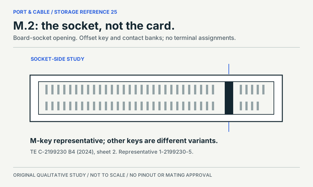
P030 / Board socket
M.2 socket
An offset key interrupts the socket opening.
TE C-2199230 B4; M-key representative 1-2199230-5. Manufacturer-drawing study; not inspected hardware.
Inspect the source, viewpoint and omissions → (private workspace)
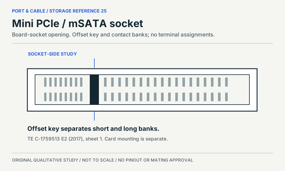
P298 / Board socket
Mini PCIe / mSATA socket
The split contact banks belong to a socket shared across distinct assignments.
TE C-1759513 E2; 1759513-1 family. Manufacturer-drawing study; not inspected hardware.
Inspect the source, viewpoint and omissions → (private workspace)
No card-to-socket compatibility arrows are drawn. Module length, thickness, retention and boot support are separate questions. Contact marks are unnumbered; they do not provide a wiring map.
03 / DRIVE INTERFACES
One view cannot show the whole connection.
The Slimline SATA panel is a manufacturer-linked component study. The SAS and 8639 panels instead show specification-level device-plug faces. Keep that evidence distinction visible when comparing them.
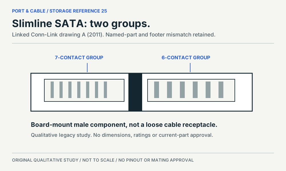
P195 / Board-mount male component
Slimline SATA
Two separated groups: seven signal contacts and six power contacts.
Conn-Link CSAT-M13RS30-Q3 linked drawing A. Legacy linked drawing; footer and current-product discrepancies remain open.
Inspect the source, viewpoint and omissions → (private workspace)
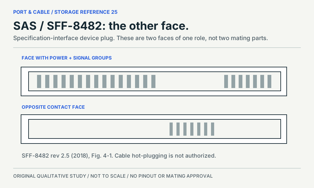
P196 / Specification-level device plug
SAS / SFF-8482
The second signal set is on the opposite face.
SFF-8482 revision 2.5 device free plug. Specification-interface study; not a named manufacturer specimen.
Inspect the source, viewpoint and omissions → (private workspace)
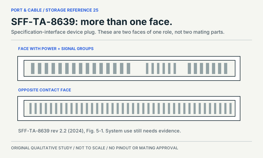
P198 / Specification-level device plug
SFF-TA-8639 / U.2–U.3 context
Additional contact regions distinguish the specification interface, not the system protocol.
SFF-TA-8639 revision 2.2 device plug. Specification-interface study; not a named manufacturer specimen.
Inspect the source, viewpoint and omissions → (private workspace)
Do not infer live-cable permission. SFF-8482 revision 2.5 section 5.3 does not support cable hot plugging. A backplane insertion sequence is not a general hot-plug guarantee. Read the scoped source ↗.
U.2 versus U.3 remains a system check. The 8639 study cannot identify routing, supported use case or compatibility from the exterior. SFF-9639 is an informational guide and explicitly sends definitive signal questions to the using-interface standards. Reference guide warning, p.7 ↗.
SOURCE TO READER / FIVE EXISTING REFERENCES
What is known. What to verify next.
P030 / Board socket
M.2 socket: Read the component role before the key name.
Next check. Read the exact host slot specification and module label; confirm interface, key, length, thickness and retention independently.
Not established. No universal M.2 speed, SATA/NVMe verdict, card-side mirror view or exact part equivalence is established.
Read 3 source-scoped findings
In TE drawing C-2199230 revision B4, the representative shown as 1-2199230-5 is an M-key board socket; the card edge is its counterpart, not the illustrated component. C030J
The C-2199230 part table separates A, B, E and M key variants, and the M-key block includes several part suffixes rather than one universal socket. C030K
The C-2199230 drawing specifies 67 contact positions with a key interruption; its two solder-tail rows have different counts, so a single visible row is not the total contact inventory. C030L
Sheets 1–3 of 4 visually inspected. Sheet 1 revision B4 dated 05 NOV 2024; sheet 2 shows 1-2199230-5 and the key/part table; sheet 3 is a PCB footprint, not a mating view. Source-checked, not independently approved. Only the observed revision is represented; current device equivalence is not established.
P298 / Board socket
Mini PCIe / mSATA socket: A shared housing does not select the interface.
Next check. Check whether the exact host routes PCIe, SATA or another documented interface, then confirm card size and retention.
Not established. No passive-adapter approval, host signal map, boot support or current mounting specification is established.
Read 3 source-scoped findings
TE drawing C-1759513 revision E2 supplies separate Mini PCI Express and mSATA signal-assignment tables for the socket family; one housing does not imply one interface assignment. C298D
The socket views in C-1759513 show two contact rows interrupted by an offset key, with short and long contact banks; the study is of the board socket, not a miniature M.2 module. C298E
C-1759513 sheet 2 separates half-size and full-size card mounting keepouts, so the socket alone does not describe the complete module-retention arrangement. C298F
Sheets 1–2 of 5 visually inspected. Sheet 1 revision E2, 05 JUN 2017: socket views and separate interface-assignment tables. Sheet 2: half/full-size card mounting keepouts. Source-checked, not independently approved. Only the observed revision is represented; current device equivalence is not established.
P195 / Board-mount male component
Slimline SATA: Keep the part label and legacy drawing warning together.
Next check. Confirm the exact drive and cable documents. Resolve the linked drawing identity discrepancy before selecting a replacement part.
Not established. Current geometry, ratings, material and temperature are unresolved; conflicting values are not promoted.
Read 3 source-scoped findings
Conn-Link describes CSAT-M13RS30-Q3 as a 7+6-position Slimline SATA male, right-angle, surface-mount component. C195D
The PDF linked from CSAT-M13RS30-Q3 shows two separated contact groups in a board-mount component; its PCB layout is a different view from the mating interface. C195E
The linked legacy drawing names CSAT-M13RS30-Q3 in its body but gives CSAT-M22-0C5 as its footer drawing number; current part equivalence is not resolved by that document alone. C195F
S596 · Conn-Link Technology ↗ · S597 · Conn-Link Technology ↗
Single PDF sheet visually inspected; revision A, 03/14/11. Body names CSAT-M13RS30-Q3 and describes 7+6P male right-angle SMT. Footer drawing number reads CSAT-M22-0C5. Source-checked, not independently approved. Only the observed revision is represented; current device equivalence is not established.
P196 / Specification-level device plug
SAS / SFF-8482: The backplane and cable receptacles are different roles.
Next check. Identify the drive, controller and fixed connector role. Use the equipment instructions for insertion, removal and power state.
Not established. No installed-system support, reciprocal SATA/SAS compatibility, current cable assembly or hot-plug permission is established.
Read 3 source-scoped findings
SFF-8482 revision 2.5 distinguishes the device free plug from fixed backplane and fixed cable receptacles; their roles and retention context are not interchangeable labels. C196C
SFF-8482 describes two seven-contact signal sets and a fifteen-contact power set; the second signal set is on the opposite side of the device plug. C196D
SFF-8482 revision 2.5 section 5.3 describes backplane insertion sequencing but states that cable hot plugging is not supported by that interface; a familiar plug outline is not a live-cable permission. C196E
Rev 2.5, 2018-08-31. Document pp.7–8 terminology/contact sets, p.10 Figure 4-1 device free plug, p.17 section 5.3. PDF zero-based pages 8 and 10 visually inspected. Source-checked, not independently approved. Only the observed revision is represented; current device equivalence is not established.
P198 / Specification-level device plug
SFF-TA-8639 / U.2–U.3 context: A common connector is not a common system.
Next check. Match the exact drive, backplane, controller and cable to the applicable interface documentation. Keep U.2 and U.3 routing questions open until then.
Not established. The exterior alone does not identify U.2 versus U.3, certify lane routing or authorize an adapter or live connection.
Read 4 source-scoped findings
SFF-TA-8639 revision 2.2 defines a 68-contact system, while SFF-9639 explains that a device plug may populate only the contacts required by its use case. C198B
The device plug in SFF-TA-8639 Figure 5-1 has contact areas on opposite faces and additional fine-contact regions; one front-facing photograph cannot show the whole interface. C198C
SFF-TA-8639 revision 2.2 section 5.2 says its fixed-connector footprint is not generally a replacement for SFF-8482 or SFF-8630 footprints. C198D
SFF-9639 revision 2.2 is informational and directs readers to the using-interface standards for definitive signal definitions; it warns that its own tables may become inaccurate. C198E
Rev 2.2, 2024-05-06. Sections 4.1 and 5.2; printed pp.15–16 Figures 5-1/5-2 visually inspected (PDF indices 14–15). Source-checked, not independently approved. Only the observed revision is represented; current device equivalence is not established.
OBSERVED DISAGREEMENTS / NOT HIDDEN
When the documents disagree, retain the limit.
Slimline SATA: linked does not mean reconciled.
The Conn-Link drawing names CSAT-M13RS30-Q3 in its body but carries a different footer drawing number. Its material and lower-temperature statements also differ from the product page. The new reference does not promote any of those disputed values or claim exact current-part geometry.
Legacy drawing A, 2011 ↗ · Named product page ↗.
M.2: the drawing revision, not the file title.
The acquired TE PDF metadata says B3 while the observed drawing title blocks say B4. The study records B4, dated 5 November 2024, without claiming it is the latest revision. Inspected drawing ↗.
All source observations were made on 13 October 2026. Source PDFs, manufacturer figures and screenshots are linked but not redistributed. Original vector studies and factual paraphrases still require independent technical and rights review.
BENCH REFERENCE / LETTER + A4
Keep the distinctions beside the hardware.
Three pages: card sockets, drive interfaces, then the source-and-check ledger. These are unscaled recognition studies, not installation instructions.
Letter reference (3 pages) ↓ (legacy download held for current evidence review). Current focused printable references · A4 reference (3 pages) ↓ (legacy download held for current evidence review). Current focused printable references
COVERAGE / STILL IN PROGRESS
Five first-study gaps closed. The rest stays visible.
This round does not complete storage coverage. Exact commercial specimens for the specification-only interfaces, current-source reconciliation and installed-system evidence remain open. Earlier PSU-image requests and the 3-pin fan image gap are unchanged.
Read the measured coverage queue → · Open the Visual Atlas → · Browse internal connectors →