
PORT & CABLE / INTERNAL REFERENCE 24
Same count.
Different job.
Fan, front-panel and lighting headers can look deceptively alike. Start with the role, then read the exact board label and manual.
Before handling. Follow the exact equipment instructions, shut down, switch off the supply and unplug the power cord before component changes. Never force or rewire an uncertain connector. MSI v6.0, p.5 ↗.
01 / FAN CONTROL
More contacts do not settle the mode.
Keep the fan's supply voltage, its control method and the board header's setting as separate checks. The observed MSI board and the Noctua family documentation answer different parts of the question.
P343 / PHYSICAL IMAGE OPEN
3-pin fan
Three positions; the exact housing has not been visually qualified here.
Noctua 3-pin fan family (bounded FAQ scope). FAQ: 3-pin fans on 4-pin headers; source re-observed 2026-10-13, canonical S454 date retained.
Inspect source, viewpoint and omissions → (private workspace)
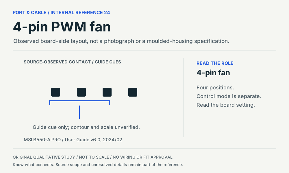
P344 / SOURCE-OBSERVED HEADER LAYOUT
4-pin fan
Four aligned contacts and a guide cue in the inspected board diagram.
MSI B550-A PRO CPU_FAN1 / PUMP_FAN1 / SYS_FAN1–6. PDF p.38 / zero-based 37, fan header locator drawings and mode table; manual version 6.0, 2024/02.
Inspect source, viewpoint and omissions → (private workspace)
The 3-pin panel is deliberately a concept, not a component drawing. Its first physical illustration remains an open coverage gap. Do not treat the two equal-size image panels as a size or mating comparison.
02 / FRONT-PANEL ROLE
USB and audio: compare the missing position.
The same board manual documents two different key arrangements. In the displayed source orientation, the USB gap is at a row end; the audio gap lies within a row. Terminal numbers and functions are intentionally omitted from the drawings.
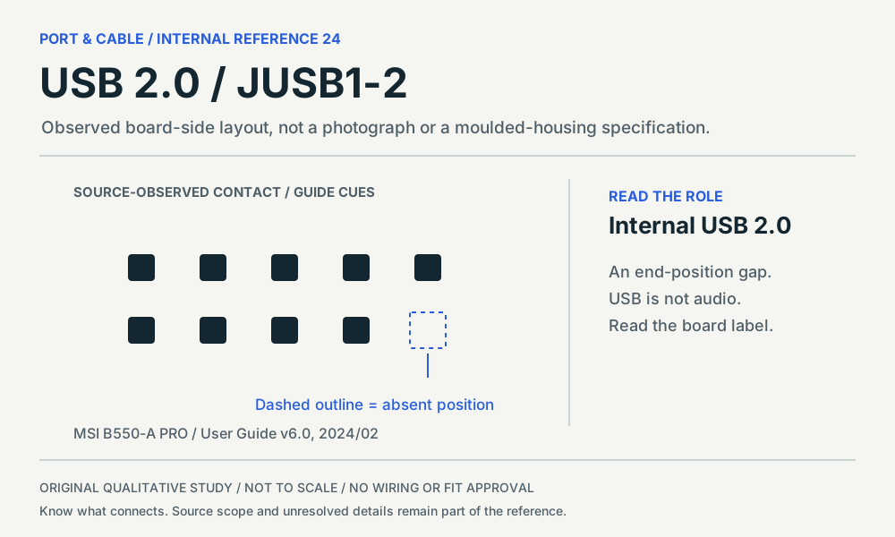
P345 / SOURCE-OBSERVED HEADER LAYOUT
Internal USB 2.0
Two rows with the absent position at a row end in this source view.
MSI B550-A PRO JUSB1–2. PDF p.37 / zero-based 36, JUSB1–2 diagram and table; version 6.0, 2024/02.
Inspect source, viewpoint and omissions → (private workspace)
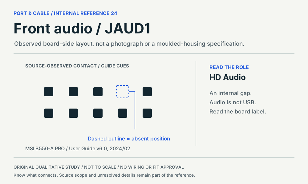
P346 / SOURCE-OBSERVED HEADER LAYOUT
HD Audio
Two rows with an internal gap, not the USB row-end gap in the same manual.
MSI B550-A PRO JAUD1. PDF p.33 / zero-based 32, JAUD1 diagram and table; version 6.0, 2024/02.
Inspect source, viewpoint and omissions → (private workspace)
These are board-side layouts from MSI B550-A PRO User Guide v6.0, not cable-side mirror views. JUSB1–2, p.37 ↗ · JAUD1, p.33 ↗. “No pin” and “not connected” describe different conditions; read the exact source rather than treating every unused position as a key.
03 / LIGHTING INTERFACE
12V RGB is not 5V ARGB.
Keep the lighting connector distinct from the fan-motor connector. The manufacturer's warning about a 5V strip on JRGB is a reason to stop, not to search for an improvised adapter.
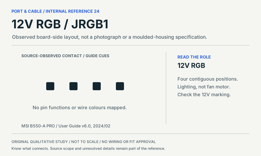
P347 / SOURCE-OBSERVED HEADER LAYOUT
12V RGB
Four contiguous positions in the JRGB1 source diagram.
MSI B550-A PRO JRGB1. PDF p.40 / zero-based 39, JRGB1 diagram; p.41 mismatch warning; version 6.0, 2024/02.
Inspect source, viewpoint and omissions → (private workspace)
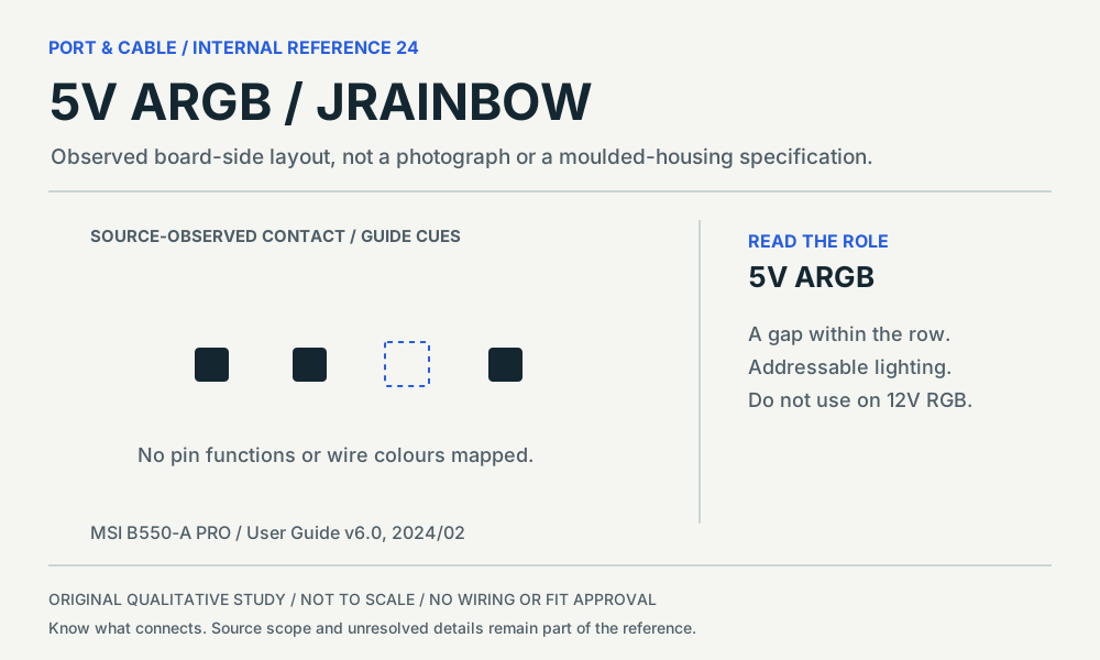
P348 / SOURCE-OBSERVED HEADER LAYOUT
5V ARGB
Three contacts across four positions, with an internal gap in the inspected view.
MSI B550-A PRO JRAINBOW1–2. PDF p.41 / zero-based 40, JRAINBOW diagram/table and caution; version 6.0, 2024/02.
Inspect source, viewpoint and omissions → (private workspace)
Mismatch warning. MSI warns of damage when a 5V LED strip is connected to JRGB. The addressable header's gap does not certify a different vendor's three-pin layout. MSI caution, p.41 ↗.
SOURCE TO READER / SIX EXISTING REFERENCES
What is known. What to verify next.
P343 / Fan cable end / counterpart header
3-pin fan: Fan control and voltage still need separate evidence.
Next check. Read the fan voltage label and the exact board fan-control mode; retain the physical-image request.
Not established. Exact 3-pin housing, key profile, installed header and permitted load.
Read three source-scoped findings
For Noctua’s described 3-pin fan connection to a 4-pin header, the separate PWM position remains unused. C343C
Noctua says automatic control can depend on motherboard voltage regulation; pulsing power is not equivalent to lowering the supply voltage. C343D
Noctua documents fans across 5V, 12V and 24V families; a contact-count label is not a voltage identification. C343E
Source-checked, not independently approved. The fan FAQ observation is reused without changing its inherited canonical source date. The new claims have their own observation dates.
P344 / Board header
4-pin fan: Contact count does not select the control mode.
Next check. Verify board model, header label, configured mode and the fan rating.
Not established. Exact connector manufacturer, housing dimensions and installed fan approval.
Read three source-scoped findings
Noctua distinguishes the female fan-cable connector from male PCB headers and male cable connectors. C344C
Noctua’s PWM white paper covers 5V, 12V and 24V four-pin models unless otherwise stated. C344D
B550-A PRO lists Auto for CPU_FAN1, PWM for PUMP_FAN1 and DC for SYS_FAN1–6 as default modes. C344E
Source-checked, not independently approved. The fan FAQ observation is reused without changing its inherited canonical source date. The new claims have their own observation dates.
P345 / Board header
Internal USB 2.0: A front-panel USB header, not the audio header.
Next check. Read the board label and exact header diagram before selecting a front-panel cable.
Not established. Unidentified board variant, cable orientation and any proprietary front-panel harness.
Read three source-scoped findings
B550-A PRO assigns JUSB1–2 to front-panel USB 2.0 ports, separately from JUSB3 and JUSB4. C345C
Its JUSB1–2 table distinguishes absent position 9 from present but unconnected position 10. C345D
MSI warns that incorrect USB-header power/ground connections can damage equipment. C345E
Source-checked, not independently approved. The fan FAQ observation is reused without changing its inherited canonical source date. The new claims have their own observation dates.
P346 / Board header
HD Audio: A front-panel audio role, not a USB role.
Next check. Find the audio header designation and the case audio-harness documentation.
Not established. AC’97 alternatives, proprietary audio harnesses and exact mating dimensions.
Read three source-scoped findings
B550-A PRO identifies JAUD1 as the front-panel audio-jack connector. C346C
JAUD1’s table distinguishes absent position 8 from unconnected position 4. C346D
The JAUD1 table includes microphone/headphone detection functions; it is not a USB signal table. C346E
Source-checked, not independently approved. The fan FAQ observation is reused without changing its inherited canonical source date. The new claims have their own observation dates.
P347 / Board header
12V RGB: Lighting control is distinct from fan-motor control.
Next check. Identify the lighting supply and header label; do not substitute an ARGB strip.
Not established. Strip/controller compatibility, total lighting load and proprietary lighting systems.
Read three source-scoped findings
B550-A PRO describes JRGB1 as a four-position 12V 5050 RGB-strip connection. C347C
MSI’s RGB-fan diagram separates the lighting lead from the system-fan connection. C347D
MSI warns that connecting a 5V LED strip to JRGB can damage the strip. C347E
Source-checked, not independently approved. The fan FAQ observation is reused without changing its inherited canonical source date. The new claims have their own observation dates.
P348 / Board header
5V ARGB: Addressable lighting is a different documented interface.
Next check. Verify the exact 5V addressable header and LED/controller documentation.
Not established. Other vendors’ three-pin arrangements, signal implementations and assembled-device approval.
Read three source-scoped findings
B550-A PRO describes JRAINBOW1–2 as 5V WS2812B addressable-LED connections. C348C
The JRAINBOW source diagram leaves position 3 absent within a four-position span. C348D
MSI requires power-supply shutdown and disconnection from the outlet before LED-strip changes. C348E
Source-checked, not independently approved. The fan FAQ observation is reused without changing its inherited canonical source date. The new claims have their own observation dates.
BENCH REFERENCE / LETTER + A4
Keep the distinctions in view.
Two pages: a comparison sheet, then a source-and-check ledger. Original diagrams remain qualitative and unapproved for wiring or installation.
Letter reference (2 pages) ↓ (legacy download held for current evidence review). Current focused printable references · A4 reference (2 pages) ↓ (legacy download held for current evidence review). Current focused printable references
DOCUMENT SCOPE / 13 OCTOBER 2026
Specific sources, visible limits.
The inspected MSI manual declares version 6.0, February 2024. This run did not establish whether it is still the latest posted revision. The Noctua white paper's publication revision was not identified. Both are bounded source observations, not current-device equivalence or independent hardware tests.
The five new physical-study entries are source-observed header-layout studies: contact arrangement and, where shown, a guide cue. They do not supply a moulded-housing specification. The 3-pin fan image, older exact PSU-image requests and all independent technical/rights approvals remain open.
Read the measured coverage queue → · Open the Visual Atlas → · Browse the internal connector reference →