
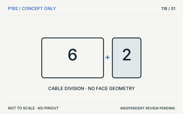
 (private workspace)
P192 / Concept — not physical geometry
PCIe / auxiliary
CORSAIR PCIe cable example
6+2 groups, not a mating face · Concept only
Not to scale. Technical and rights review pending.
Inspect view & provenance (private workspace)P192 / PC power / Connector
The legacy PCI Express auxiliary-power family includes an eight-position 2x4 connector form.
Also called PCIe 8 pin GPU 8 pin 6+2 PCIe power 2x4 PCIe power
A 6+2 cable example is not an EPS12V 4+4 cable. Device location alone is not a reliable identity test.
Use the PSU cable label and add-in-card documentation; compare keying and intended connector family rather than pin count alone.
Claim inspection dates: 2026-10-05, 2026-10-11, 2026-10-12 · Independent review pending
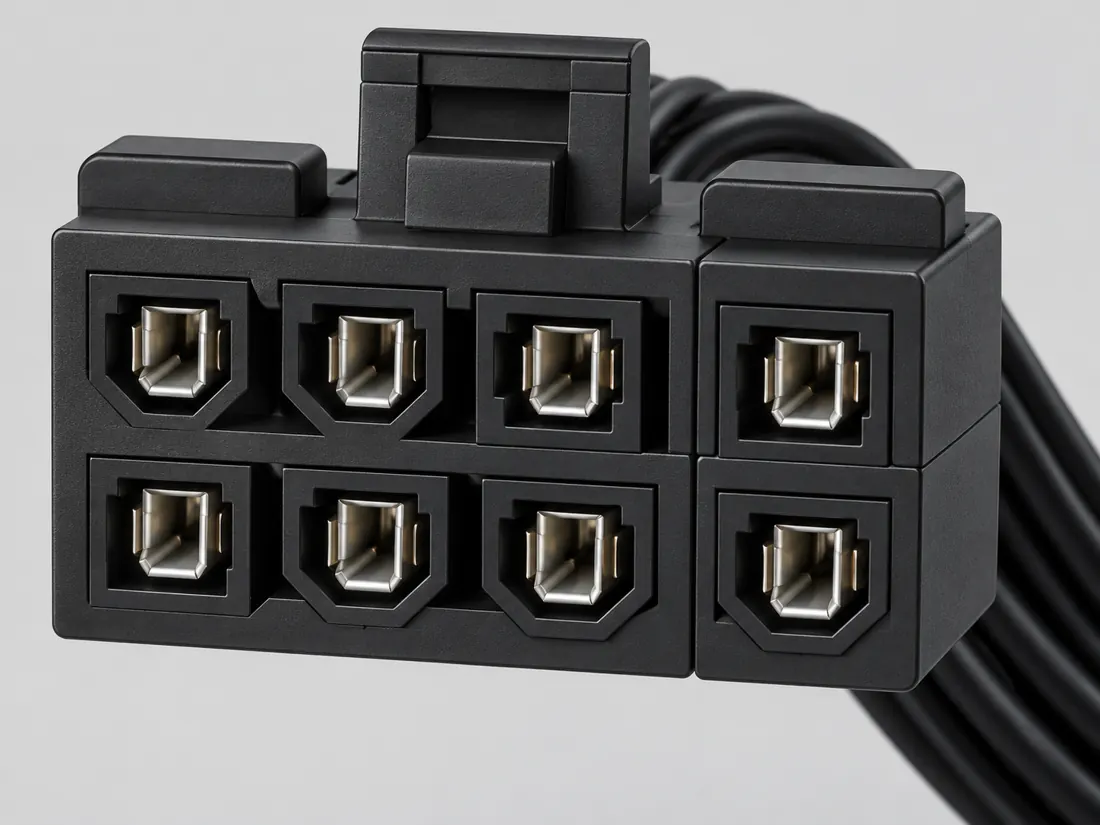
Three-quarter view Computer-generated illustration with prior AI visual review. Not a photograph, measurement or compatibility check. Independent technical and rights review pending.
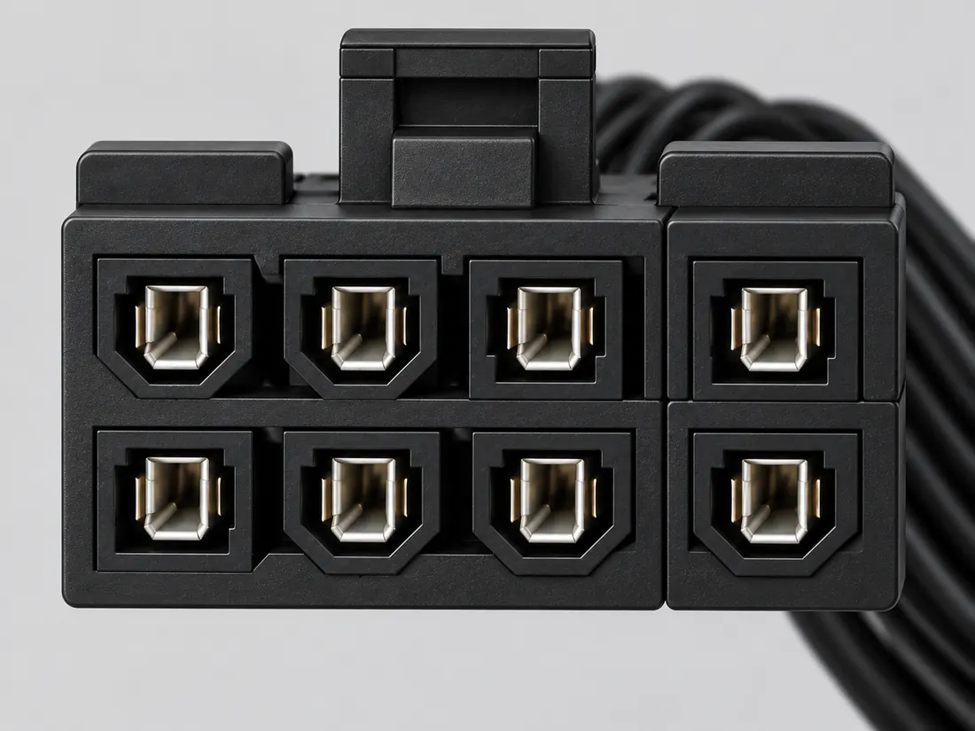
Mating face Computer-generated illustration with prior AI visual review. Not a photograph, measurement or compatibility check. Independent technical and rights review pending.
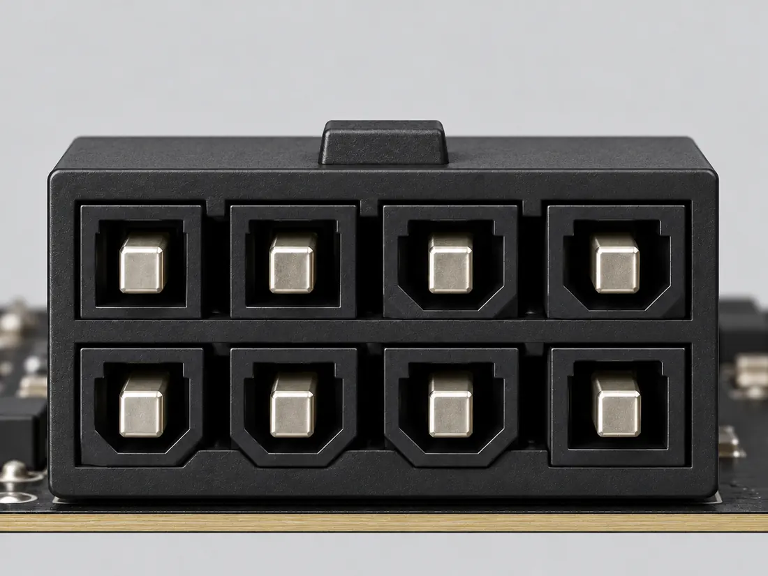
Fitted in place Computer-generated illustration with prior AI visual review. Not a photograph, measurement or compatibility check. Independent technical and rights review pending.
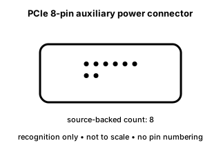
Recognition drawing Original schematic, not to scale. Drawing review pending.
Image inspection / P192
1 registered view for this reference. Different part examples are not automatically mates; all remain not to scale and independently unapproved.
(private workspace)P192 / Concept — not physical geometry
CORSAIR PCIe cable example
6+2 groups, not a mating face · Concept only
Not to scale. Technical and rights review pending.
Inspect view & provenance (private workspace)Matching notes / PC power / P192
Eight positions do not establish cable identity. The 6+2 PCIe example and the 4+4 CPU example have distinct component roles.
Read the PCIe designation and the exact device and PSU documentation together.
CORSAIR warns that incorrect modular cable types can damage hardware. Location on a motherboard is not proof that the cable is EPS.
The wire assignment of an unlabeled modular cable is not established by this guide.
C192A (private workspace) — Intel documents a 2x4 PCIe add-in-card auxiliary-power connector form in the cited ATX design guide.
V36 catalogue-expansion identification fact only; not independent technical approval, fabrication data, wiring instruction or end-to-end compatibility proof. S199
C192C (private workspace) — CORSAIR describes the eight-position PCIe cable end as a 6+2 arrangement and distinguishes it from EPS12V; some motherboards also use PCIe power connectors.
Do not infer cable role solely from the equipment category or position count. S474
C192D (private workspace) — CORSAIR warns that using the incorrect modular PSU cable type may damage hardware and requires cable-type verification before installation.
The component-end PCIe role is separate from exact CORSAIR PSU cable compatibility; no cross-brand pinout is inferred. S489
Manufacturer evidence is not an independent review, wiring assignment or hardware test.
Visual atlas / Series 02 / P192
What this view supports
Cavity keying, wire colors, pin maps and compatibility are intentionally not drawn.
Why no physical view? Linked manufacturer exterior image could not be inspected; no guessed physical housing.
The next useful check
Confirm the PCIe label and the exact equipment and PSU manuals. Keep the modular PSU-end wiring decision separate.
C192C CORSAIR describes the eight-position PCIe cable end as a 6+2 arrangement and distinguishes it from EPS12V; some motherboards also use PCIe power connectors.
Do not infer cable role solely from the equipment category or position count. Source checked 2026-10-11; independent review pending. S474 · Evidence trail → (private workspace)
Visual inspection 2026-10-11. AI-assisted source inspection; independent drawing and rights reviews pending. These are original qualitative interpretations, not mechanical drawings, pinouts or approved connections.
Independent simplified vector interpretation and original factual paraphrase only. No manufacturer image, PDF, CAD, logo or traced path is redistributed. Independent technical and rights assessment remains pending.
4-pin ATX12V / 8-pin EPS12V and 6-pin / 6+2-pin PCIe sections. Text inspected; linked product images could not be retrieved.
Split-cable examples and CPU/PCIe role distinction only. No physical mating-face art is authorized by this text inspection. Only the exact named source/example supports the observation. No universal mating, wiring, maximum rating or mechanical tolerance is inferred. Not identified; retrieval is not a revision date.
PCIe auxiliary power connector section
Identifies legacy 2x3 and 2x4 PCIe auxiliary-power forms and the 12VHPWR form with twelve larger power contacts plus four smaller sideband contacts. Identification/reference scope only. V36 does not convert this source into a universal pinout, fabrication drawing, electrical approval or end-to-end compatibility verdict.
Canonical evidence is retained separately. Existing claim dates are unchanged; only new V118 claims have a new inspection date. No live electrical, energized probing, forced mating or optical-port inspection is recommended.
No automatic cross-use follows from the 2×4 silhouette. Intel identifies the PCIe eight-position auxiliary interface as distinct from the processor +12 V connector. A 6+2 assembly is a cable configuration used in the PCIe card-power context, not a license to interchange with EPS/CPU 4+4 or an arbitrary PSU modular port.
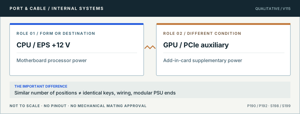
Deciding CPU/GPU cable type by contact count without reading the PSU cable’s own marking.
Full technical reading, sources and related identities →Claim-specific evidence remains in the canonical record. Concept diagrams do not show any safe wiring or mechanical mating geometry.
The useful distinction
The legacy PCI Express auxiliary-power family includes an eight-position 2x4 connector form. [C192A]
CORSAIR describes the eight-position PCIe cable end as a 6+2 arrangement and distinguishes it from EPS12V; some motherboards also use PCIe power connectors. [C192C]
CORSAIR warns that using the incorrect modular PSU cable type may damage hardware and requires cable-type verification before installation. [C192D]
Intel revision 2.11 describes the PCIe 2x4 connection as a board header and a separate cable-plug harness; these are different component roles. [C192E]
CORSAIR documents PCIe-power inputs on some motherboards as well as graphics cards; mounting on a motherboard does not by itself identify an EPS12V input. [C192F]
Distinguish PCIe auxiliary power from CPU/EPS power even when counts match.
| Nominal contacts | 8S199Documented position count only; no V36 electrical pin map. |
|---|---|
| Positions / cavity span | 8 (Claim C192C)S474Recorded source-scoped values; named examples do not describe every family variant or establish compatibility. Do not infer cable role solely from the equipment category or position count. |
| Populated contacts | Not recordedNot recorded in a normalized source-scoped field. Consult the exact part/revision; no value inferred from illustrations. |
| Connector role | plug; headerS199 · S216Recorded source-scoped values; named examples do not describe every family variant or establish compatibility. PCIe auxiliary-power cable plug / add-in-card header interface |
| Contact rows | 2 (Source-described array; C192A); 2 (Source-described array; C192B); 2 (Source-described array; C192E)S199 · S216 · S561Recorded source-scoped values; named examples do not describe every family variant or establish compatibility. V36 catalogue-expansion identification fact only; not independent technical approval, fabrication data, wiring instruction or end-to-end compatibility proof. V37 engineering-depth sidecar fact; source-checked but not independently human-approved, not a fabrication drawing, and not a safe-substitution or repair instruction. Printed page 59 only. The guide-specific connection description is not a PSU-side socket assignment or permission to reuse an unknown cable. |
|---|---|
| Contact pitch | 4.2 mm manufacturer-reported centerline or mating-interface pitch (NVIDIA GRID K2 eight-pin PCIe power header)S765Separate exact examples; retain each value’s source, role, axis and part scope. Exact named example NVIDIA GRID K2 eight-pin PCIe power header: Device-specific board header. Exact example only; no universal geometry, electrical compatibility, fabrication approval or wiring instruction. Named2013board example only. Do not treat as every modernGPUheader geometry or modularPSU pinout. |
| Dimensions / axis | 18 ± 0.25 mm housing width (NVIDIA GRID K2 eight-pin PCIe power header); 11.4 ± 0.25 mm housing height (NVIDIA GRID K2 eight-pin PCIe power header); 18.1 ± 0.25 mm front-to-rear overall connector extent including formed PCB tails (NVIDIA GRID K2 eight-pin PCIe power header)S765Separate exact examples; retain each value’s source, role, axis and part scope. Exact named example NVIDIA GRID K2 eight-pin PCIe power header: Device-specific board header. Exact example only; no universal geometry, electrical compatibility, fabrication approval or wiring instruction. Named2013board example only. Do not treat as every modernGPUheader geometry or modularPSU pinout. |
| Coupling / latch | Not recordedNot recorded in a normalized source-scoped field. Consult the exact part/revision; no value inferred from illustrations. |
| Keying / polarization | position1indicator and alignment rib shown in Figure7 (NVIDIA GRID K2 eight-pin PCIe power header)S765Separate exact examples; retain each value’s source, role, axis and part scope. Exact named example NVIDIA GRID K2 eight-pin PCIe power header: Device-specific board header. Exact example only; no universal geometry, electrical compatibility, fabrication approval or wiring instruction. Named2013board example only. Do not treat as every modernGPUheader geometry or modularPSU pinout. |
| View convention | Figure7 front/side/section views of board header; position1indicator and alignment rib explicit; not cable wire-entry map (NVIDIA GRID K2 eight-pin PCIe power header)S765Separate exact examples; retain each value’s source, role, axis and part scope. Exact named example NVIDIA GRID K2 eight-pin PCIe power header: Device-specific board header. Exact example only; no universal geometry, electrical compatibility, fabrication approval or wiring instruction. Named2013board example only. Do not treat as every modernGPUheader geometry or modularPSU pinout. |
| Contact gender / arrangement | Not recordedNot recorded in a normalized source-scoped field. Consult the exact part/revision; no value inferred from illustrations. |
| Mounting | board (Claim C192E)S561Recorded source-scoped values; named examples do not describe every family variant or establish compatibility. Printed page 59 only. The guide-specific connection description is not a PSU-side socket assignment or permission to reuse an unknown cable. |
| Shell / form | Not recordedNot recorded in a normalized source-scoped field. Consult the exact part/revision; no value inferred from illustrations. |
| Manufacturer | Not recordedNot recorded in a normalized source-scoped field. Consult the exact part/revision; no value inferred from illustrations. |
| Series | Not recordedNot recorded in a normalized source-scoped field. Consult the exact part/revision; no value inferred from illustrations. |
| Exact part / implementation | NVIDIA GRID K2 eight-pin PCIe power header (NVIDIA GRID K2 eight-pin PCIe power header)S765Separate exact examples; retain each value’s source, role, axis and part scope. Exact named example NVIDIA GRID K2 eight-pin PCIe power header: Device-specific board header. Exact example only; no universal geometry, electrical compatibility, fabrication approval or wiring instruction. Named2013board example only. Do not treat as every modernGPUheader geometry or modularPSU pinout. |
| Recorded markings | Not recordedNot recorded in a normalized source-scoped field. Consult the exact part/revision; no value inferred from illustrations. |
Keep this limit: An incorrect modular PSU cable type can damage hardware; do not infer a universal PSU-side mapping. S489
Check the exact PSU cable type and the board/card connector designation in both manuals.
Existing source inspection and AI review remain distinct from independent technical review. A matching form does not establish a safe connection.
Bounded facts, visible unknowns
| Documented identification | 8-position 2x4 PCIe auxiliary-power form. [C192A] |
|---|---|
| Mechanical dimensions | No independently reviewed mechanical drawing in V36; do not use this page for fabrication, fit testing or tolerance work. |
| Engineering pinout | Source-checked engineering profile available; independent review pending. Open engineering profile → |
| Verified device list | Not included. Check exact device and accessory documentation. |
Use the source-backed form or position count only for identification. Resolve ratings, protocol, direction, wiring, cable construction and exact device support from the relevant equipment and component documentation.
Before you connect
Pins & wiring
Choose the exact wiring. Pin numbers follow its stated view; a schematic does not establish physical positions. Check your exact device before wiring.
This field note does not approve a connection, adapter, cable assembly, rewiring scheme or fabricated part. It intentionally omits unsupported pin assignments and mechanical tolerances.
Your next step
The source trail
AI-assisted inspection is not independent engineering review. Source scope and access limitations are disclosed below. Procedural checklists are editorial requirements, not hardware measurements.
Intel documents a 2x4 PCIe add-in-card auxiliary-power connector form in the cited ATX design guide.
Intel · ATX Version 3.0 — PCI Express add-in card connectors ↗S199: full source recordInspect review dependencies → (private workspace)CORSAIR describes the eight-position PCIe cable end as a 6+2 arrangement and distinguishes it from EPS12V; some motherboards also use PCIe power connectors.
CORSAIR · Which PSU cables go where? — EPS and PCIe sections ↗S474: full source recordInspect review dependencies → (private workspace)CORSAIR warns that using the incorrect modular PSU cable type may damage hardware and requires cable-type verification before installation.
CORSAIR · PSU cable compatibility — Type 3/4 versus Type 5 warning ↗S489: full source recordInspect review dependencies → (private workspace)Intel revision 2.11 describes the PCIe 2x4 connection as a board header and a separate cable-plug harness; these are different component roles.
Intel · Intel ATX12VO Design Guide revision 2.11 — role and generation boundaries ↗S561: full source recordInspect review dependencies → (private workspace)CORSAIR documents PCIe-power inputs on some motherboards as well as graphics cards; mounting on a motherboard does not by itself identify an EPS12V input.
CORSAIR · CORSAIR power-cable guide — required inputs and connector location ↗S560: full source recordInspect review dependencies → (private workspace)Follow the connection
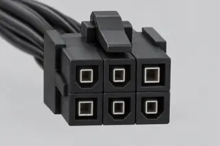
A PCIe auxiliary-power connector is not a general-purpose keyed DC connector.
Open field note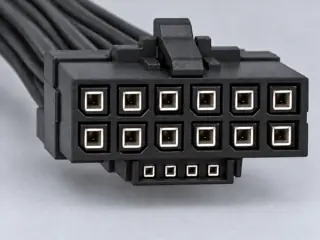
The newer 16-contact form is a separate connector family from the older 2x3 and 2x4 PCIe auxiliary connectors.
Open field note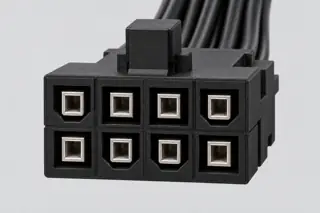
An eight-position PC power shell can be confused with PCIe auxiliary power; keying and device documentation matter.
Open field noteCompare look-alikes: 8-pin CPU power versus 8-pin PCIe auxiliary power · Legacy PCIe auxiliary power versus 12VHPWR · PCIe 8-pin, 12VHPWR and 12V-2x6 auxiliary power
Candidate selection does not confirm the identity or capabilities of your physical item.
Use this reference
PC power / Several identities remain possible
Read the exact CPU/GPU and PSU-side cable documentation. A concept illustration is not a cavity-key map.
P190 reference · P192 reference · Inspect named view (private workspace)
The illustration cannot approve a CPU/GPU substitution or PSU-side cable interchange.
PC power / Unconfirmed candidate
Record both cable ends and the exact power-supply model before checking a replacement.
P192 reference · P190 reference · Inspect named view (private workspace)
No PSU-side interchangeability is carried from this image.
POWER ROLES / COMPONENT & DOCUMENT IDENTITY
Intel ATX12VO Design Guide revision 2.11 — role and generation boundaries ↗
Revision 2.11 / May 2024. Printed pages 17, 58, 59 and 63 visually inspected; page 63 special note compares 12V-2x6 and earlier 12VHPWR.
S561 · canonical observation date 2026-10-12. This specified guide revision only. It separates PCB headers from cable plugs and describes changed PCB-header contact lengths. No pinout, dimensions, sensing circuit, power rating or fit approval is imported.
CORSAIR power-cable guide — required inputs and connector location ↗
4-pin ATX12V / 8-pin EPS12V and 6-pin / 6+2-pin PCIe sections; accompanying physical images were not visually inspectable.
S560 · canonical observation date 2026-10-12. Equipment-side roles and the instruction to consult the motherboard manual. The article includes motherboard PCIe-power examples. Its images do not qualify as inspected physical specimens here.
Observation date is not a document issue date. No hardware, wiring, seating, fit or independent approval.
Observed . C192D
PSU cable compatibility — Type 3/4 versus Type 5 warning ↗
Disclaimer item 3; cable-type headings. The model chart icon cells are not interpreted.
S489 · canonical observation date 2026-10-11. CORSAIR modular PSU cable types only; not cross-brand compatibility.
Observation date is not a document issue date. No hardware, wiring, seating, fit or independent approval.
No new physical view closes this reference’s image request in V137. Concepts are not specimen substitutes.
Read the power reference and open-image ledger →