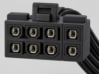
Three-quarter view Computer-generated illustration with prior AI visual review. Not a photograph, measurement or compatibility check. Independent technical and rights review pending.
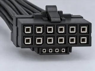
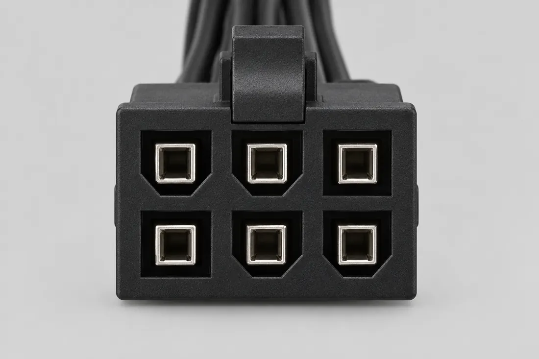
Mating face Computer-generated illustration with prior AI visual review. Not a photograph, measurement or compatibility check. Independent technical and rights review pending.
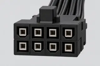
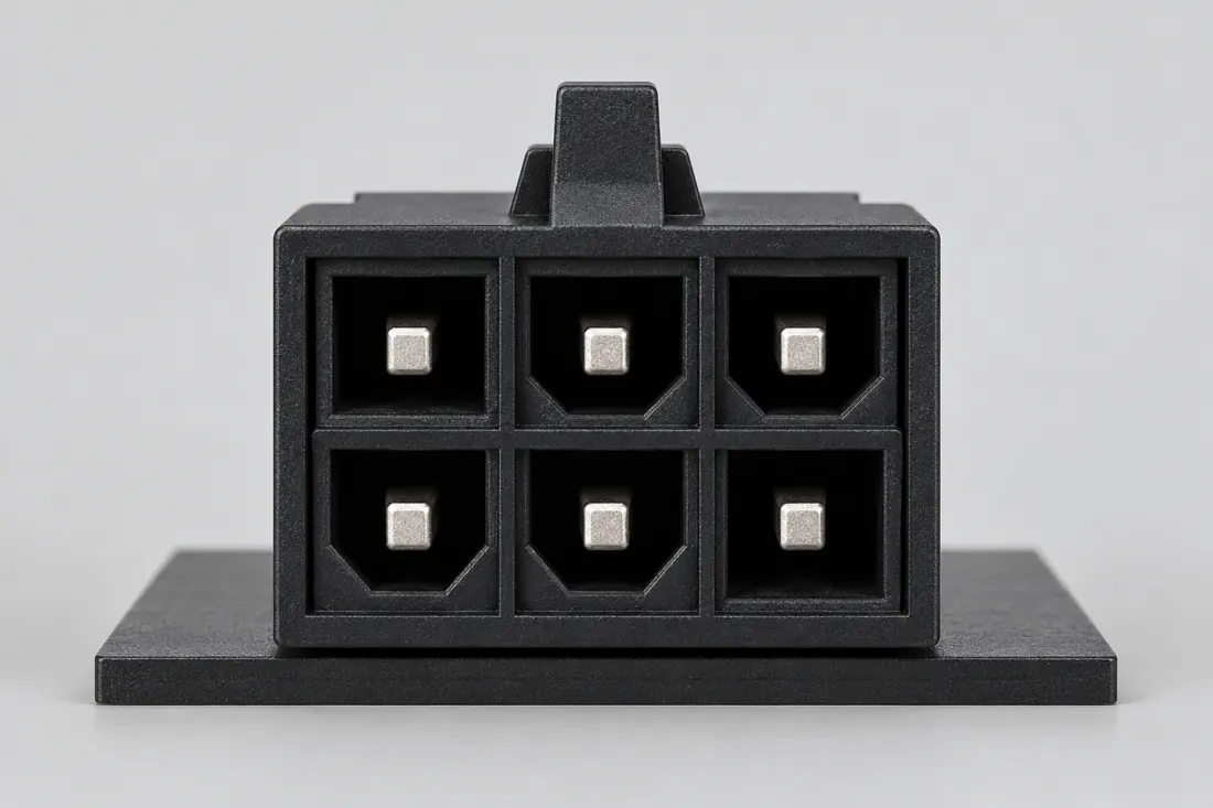
Fitted in place Computer-generated illustration with prior AI visual review. Not a photograph, measurement or compatibility check. Independent technical and rights review pending.
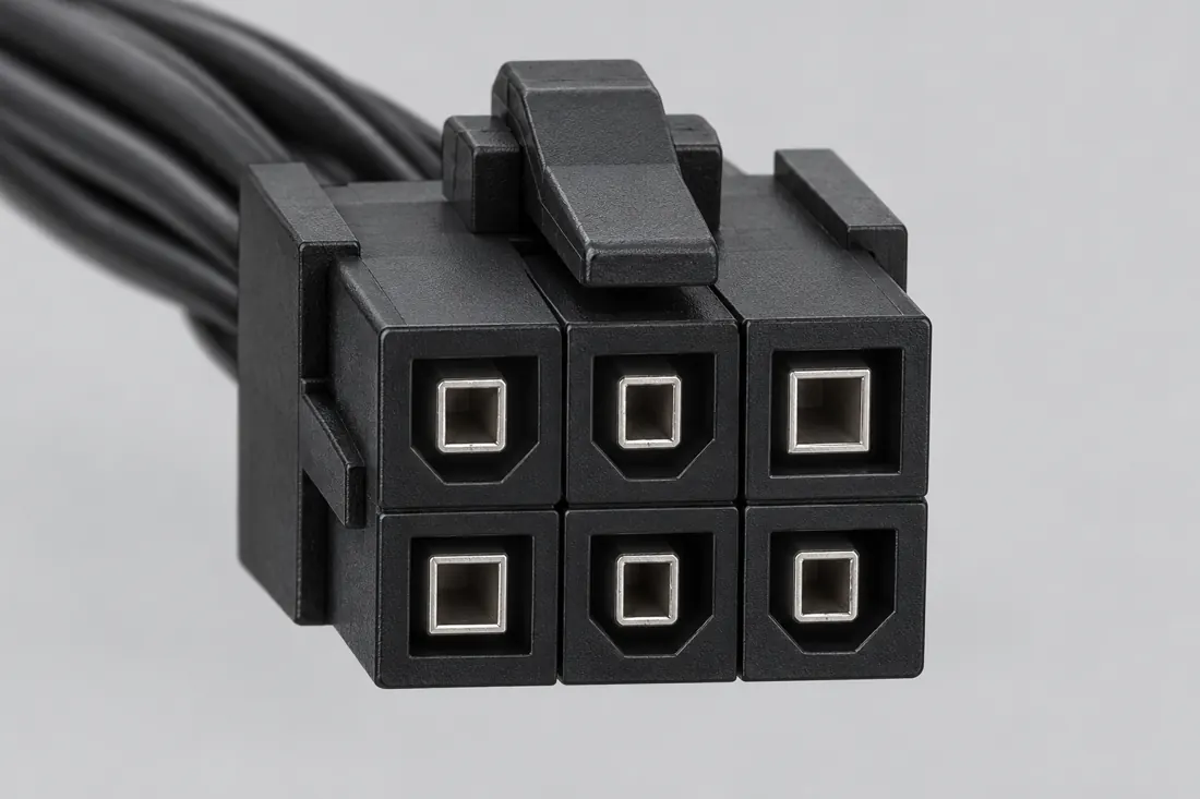
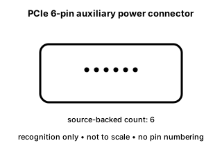
Recognition drawing Original schematic, not to scale. Drawing review pending.
Image inspection / P191
See the view. Check its scope.
1 registered view for this reference. Different part examples are not automatically mates; all remain not to scale and independently unapproved.
(private workspace)
P191 / Concept — not physical geometry
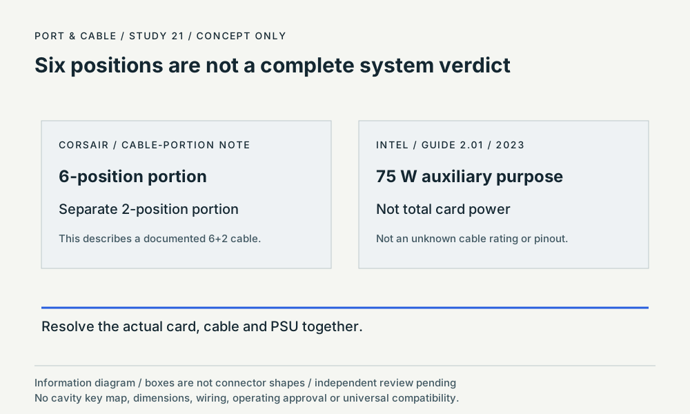
Six positions are not a complete system verdict
CORSAIR 6+2 role note / Intel 2.01 design purpose
information hierarchy · Concept only
Not to scale. Technical and rights review pending.
Inspect view & provenance ↗ (private workspace)
The useful distinction
Recognize it. Then verify it.
The legacy PCI Express auxiliary-power family includes a six-position 2x3 connector form. [C191A]
Intel design-guide version 2.01 describes the PCIe 2x3 auxiliary connector as providing 75 watts to an add-in card. This is a dated design purpose, not a tested rating for an unidentified cable. [C191C]
The PCIe 2x3 subsection of Intel guide 2.01 describes a sense connection used by the add-in card to detect an attached auxiliary-power connector; a wiring location or modification is not supplied here. [C191D]
CORSAIR describes using only the six-position portion of a 6+2 PCIe cable for a six-position connection; its small two-position portion is separate. This does not authorize an arbitrary cable or power-supply-side substitution. [C191E]
Source-scoped identification facts
Each value retains its exact example, role and measurement axis. Facts from different parts must not be combined into an invented component.
Documented examples; not a mating drawing or compatibility approval
Nominal contacts
6S199Documented position count only; no V36 electrical pin map.
Positions / cavity span
6 (PCIe six-position cable connector form)S570Recorded source-scoped values; named examples do not describe every family variant or establish compatibility. V139 Source-scoped identification only. No complete cable assembly, universal mating, pin assignment, safe operating load, installation instruction or independent approval is established.
Contact rows
2 (Source-described array; C191A); 2 (Source-described array; C191B); 2 (Source-described array; C191C); 2 (Source-described array; C191D); 2S199 · S216 · S572 · S572 · S755Named source examples retain separate role, part, view and axis limits; values are not a universal family specification. V36 catalogue-expansion identification fact only; not independent technical approval, fabrication data, wiring instruction or end-to-end compatibility proof. V37 engineering-depth sidecar fact; source-checked but not independently human-approved, not a fabrication drawing, and not a safe-substitution or repair instruction. V139 Source-scoped identification only. No complete cable assembly, universal mating, pin assignment, safe operating load, installation instruction or independent approval is established. Intel336521Rev2.1a PCIe2x3 auxiliary. Documented role: cable plug. Noexactmaker/partinferred. Molex45559-0002partpagewasreadbuttheIntelcrossreferencewasnotestablished,sothatpartisnotassignedtoPCIe6pin.; 2x3denotes2rows3positions;no newnumberedfaceorpinout is created. Rating is not standalone assembly approval.
Contact pitch
4.2 mm published2x3/2x4auxiliary contact pitchS755Named source examples retain separate role, part, view and axis limits; values are not a universal family specification. Intel336521Rev2.1a PCIe2x3 auxiliary. Documented role: cable plug. Noexactmaker/partinferred. Molex45559-0002partpagewasreadbuttheIntelcrossreferencewasnotestablished,sothatpartisnotassignedtoPCIe6pin.; 2x3denotes2rows3positions;no newnumberedfaceorpinout is created. Rating is not standalone assembly approval.
Connector role
plug; header; cable plugS199 · S216 · S755Named source examples retain separate role, part, view and axis limits; values are not a universal family specification. PCIe auxiliary-power cable plug / add-in-card header interface Intel336521Rev2.1a PCIe2x3 auxiliary. Documented role: cable plug. Noexactmaker/partinferred. Molex45559-0002partpagewasreadbuttheIntelcrossreferencewasnotestablished,sothatpartisnotassignedtoPCIe6pin.; 2x3denotes2rows3positions;no newnumberedfaceorpinout is created. Rating is not standalone assembly approval.
Series
Intel336521Rev2.1a PCIe2x3 auxiliaryS755Named source examples retain separate role, part, view and axis limits; values are not a universal family specification. Intel336521Rev2.1a PCIe2x3 auxiliary. Documented role: cable plug. Noexactmaker/partinferred. Molex45559-0002partpagewasreadbuttheIntelcrossreferencewasnotestablished,sothatpartisnotassignedtoPCIe6pin.; 2x3denotes2rows3positions;no newnumberedfaceorpinout is created. Rating is not standalone assembly approval.
Not recorded: Populated contacts, Dimensions / axis, Contact gender / arrangement, Mounting, Coupling / latch, Keying / polarization, Shell / form, Manufacturer, Exact part / implementation, Recorded markings, View convention. Unknown fields stay unknown; illustrations supply no measurements or pin assignments.
Recorded variant and source limits
No mating-face orientation or key geometry is inferred from the assignment table.
This profile is not a modular PSU-side pinout and is not a substitute for the power-supply manufacturer documentation.
Intel rev 2.1a PCIe 2x3, 75 W: Numbered assignments only. The retrieved Intel section supplies a table but no numbered mating-face or wire-side drawing; spatial orientation is UNVERIFIED. Do not mirror these numbers onto an unidentified cable end.
NVIDIA GRID K2 six-pin auxiliary connector: Use NVIDIA Figure 6 board connector drawing and its explicit #1 PIN and #4 PIN callouts. Table 2 defines numbers. No cable wire-side mapping established.
C191E / S570 separately describes the six-position PCIe connector body and the two-position detachable portion of a 6+2 cable end. The two-position portion is context only; it is not a second position count for this six-position form. Exact part, key geometry and cable assembly remain unresolved.
Not included. Check exact device and accessory documentation.
A boundary, not an omission to guess around.
Use the source-backed form or position count only for identification. Resolve ratings, protocol, direction, wiring, cable construction and exact device support from the relevant equipment and component documentation.
Before you connect
What to check
Identify the exact connector family and variant from the equipment or cable documentation.
Keep shape, contact count, protocol, electrical rating and device support as separate facts.
Do not force, rewire or adapt a connector from this recognition record; resolve the remaining requirements first.
Choose the exact wiring. Pin numbers follow its stated view; a schematic does not establish physical positions. Check your exact device before wiring.
What the status labels mean
Confirmed
Recorded research passes agree within this variant; this is not independent human review or hardware validation.
Single source
Only one underlying document, or one pass, supports this assignment.
Device-specific
Supported for the named equipment or wiring only. Check your device’s manual.
Unverified
Missing or conflicting evidence. Do not wire from this row.
Not connected
The source explicitly says NC, no contact or no pin for this wiring.
What is not established
This field note does not approve a connection, adapter, cable assembly, rewiring scheme or fabricated part. It intentionally omits unsupported pin assignments and mechanical tolerances.
AI-assisted inspection is not independent engineering review. Source scope and access limitations are disclosed below. Procedural checklists are editorial requirements, not hardware measurements.
Locator: PCIe auxiliary power connector section Access: public page. Identification/reference scope only. V36 does not convert this source into a universal pinout, fabrication drawing, electrical approval or end-to-end compatibility verdict.
Intel design-guide version 2.01 describes the PCIe 2x3 auxiliary connector as providing 75 watts to an add-in card. This is a dated design purpose, not a tested rating for an unidentified cable.
The PCIe 2x3 subsection of Intel guide 2.01 describes a sense connection used by the add-in card to detect an attached auxiliary-power connector; a wiring location or modification is not supplied here.
CORSAIR describes using only the six-position portion of a 6+2 PCIe cable for a six-position connection; its small two-position portion is separate. This does not authorize an arbitrary cable or power-supply-side substitution.
ATX guide 2.01: six-position auxiliary power scope ↗ Document 336521, version 2.01, dated 1 February 2023; PCIe 2x3 subsection, 75-watt design purpose and sense-function prose. S572 · observation date 2026-10-12. Historical guide version 2.01 explicitly has a newer-version notice. Its 75 W purpose and sense role are retained as dated design-guide facts, not a safe load for an unknown cable. No table, wiring location or jumper procedure is reproduced.
The observation date is not a drawing revision. No wiring, fit or installation approval.
Read the six-position portion
CORSAIR / 6-pin and 6+2 cable explanation
Role
Equipment-side cable example.
Distinction
The guide describes the six-position portion separately from the small two-position portion.
Established
The split identifies a documented cable arrangement, not universal modular-side compatibility.
Not established
An exact cable part number or identity from a photograph alone.
Next check
Confirm PCIe cable role and the equipment manual; do not substitute an EPS cable.
Source-field reference; no physical view assigned to this row.
ATX motherboard role and separable PCIe cable portions ↗ 24-pin ATX connector and 6-pin / 6+2-pin PCIe sections. Text inspected; article images unavailable. S570 · observation date 2026-10-12. The guide identifies motherboard main power and describes using the six-position portion of a documented 6+2 cable. It does not identify every bare housing or authorize an unknown PSU cable.
The observation date is not a drawing revision. No wiring, fit or installation approval.
Assessment 2026-10-22 · earliest scheduled source review 2027-01-03. This is a recorded-date assessment, not a live source check. Page-level independent review is not established by this panel.
Scoped support: Identifies legacy 2x3 and 2x4 PCIe auxiliary-power forms and the 12VHPWR form with twelve larger power contacts plus four smaller sideband contacts.
Not established / limitations: Identification/reference scope only. V36 does not convert this source into a universal pinout, fabrication drawing, electrical approval or end-to-end compatibility verdict.
Scoped support: The guide identifies motherboard main power and describes using the six-position portion of a documented 6+2 cable. It does not identify every bare housing or authorize an unknown PSU cable.
Not established / limitations: Source-scoped identification only. No complete cable assembly, universal mating, pin assignment, safe operating load, installation instruction or independent approval is established.
Locator: 24-pin ATX connector and 6-pin / 6+2-pin PCIe sections. Text inspected; article images unavailable.
Scoped support: Historical guide version 2.01 explicitly has a newer-version notice. Its 75 W purpose and sense role are retained as dated design-guide facts, not a safe load for an unknown cable. No table, wiring location or jumper procedure is reproduced.
Not established / limitations: Source-scoped identification only. No complete cable assembly, universal mating, pin assignment, safe operating load, installation instruction or independent approval is established.
Locator: Document 336521, version 2.01, dated 1 February 2023; PCIe 2x3 subsection, 75-watt design purpose and sense-function prose.
Trace 4 claims to their source records
C191A · P191
Intel documents a 2x3 PCIe add-in-card auxiliary-power connector form in the cited ATX design guide.
Claim scope: V36 catalogue-expansion identification fact only; not independent technical approval, fabrication data, wiring instruction or end-to-end compatibility proof.
Intel design-guide version 2.01 describes the PCIe 2x3 auxiliary connector as providing 75 watts to an add-in card. This is a dated design purpose, not a tested rating for an unidentified cable.
Claim scope: V139 Source-scoped identification only. No complete cable assembly, universal mating, pin assignment, safe operating load, installation instruction or independent approval is established.
The PCIe 2x3 subsection of Intel guide 2.01 describes a sense connection used by the add-in card to detect an attached auxiliary-power connector; a wiring location or modification is not supplied here.
Claim scope: V139 Source-scoped identification only. No complete cable assembly, universal mating, pin assignment, safe operating load, installation instruction or independent approval is established.
CORSAIR describes using only the six-position portion of a 6+2 PCIe cable for a six-position connection; its small two-position portion is separate. This does not authorize an arbitrary cable or power-supply-side substitution.
Claim scope: V139 Source-scoped identification only. No complete cable assembly, universal mating, pin assignment, safe operating load, installation instruction or independent approval is established.
Recorded evidence only. An inspection date, publisher label, source link or generated packet is not independent technical review, hardware testing, fabrication approval or a compatibility verdict.

 (private workspace)