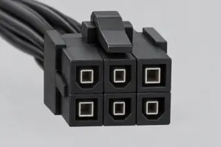
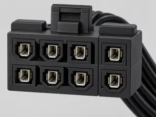
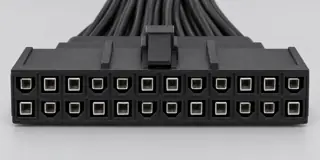
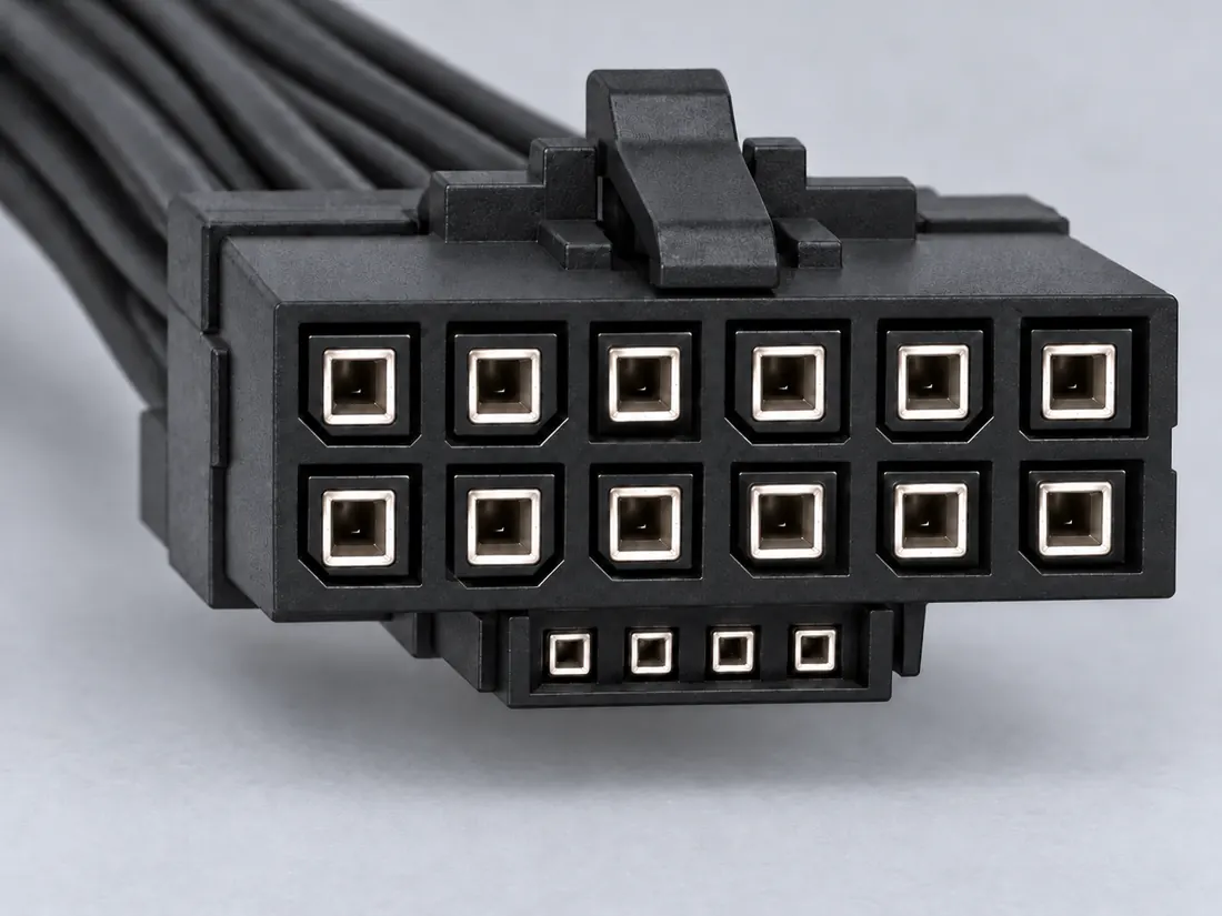
Three-quarter view Computer-generated illustration with prior AI visual review. Not a photograph, measurement or compatibility check. Independent technical and rights review pending.
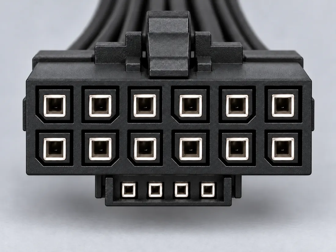
Mating face Computer-generated illustration with prior AI visual review. Not a photograph, measurement or compatibility check. Independent technical and rights review pending.
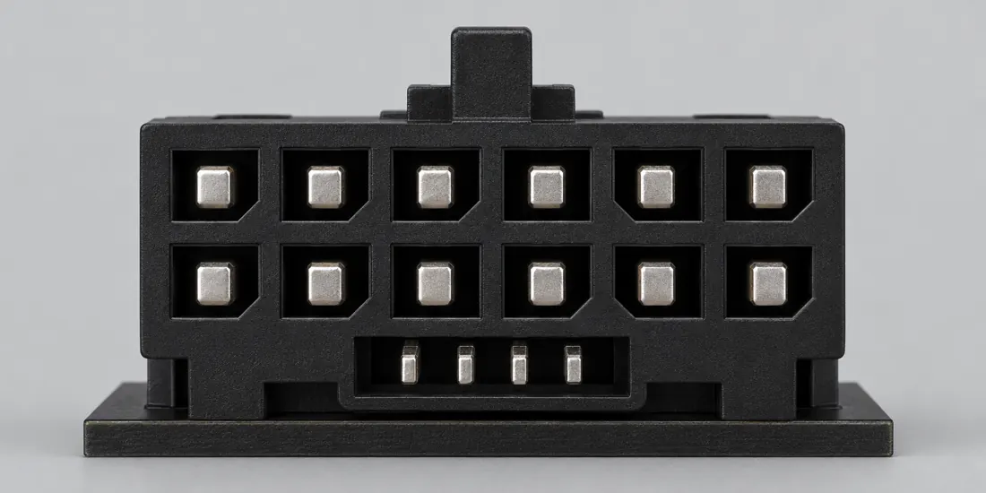
Fitted in place Computer-generated illustration with prior AI visual review. Not a photograph, measurement or compatibility check. Independent technical and rights review pending.
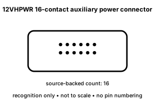
Recognition drawing Original schematic, not to scale. Drawing review pending.
Image inspection / P193
See the view. Check its scope.
2 registered views for this reference. Different part examples are not automatically mates; all remain not to scale and independently unapproved.
(private workspace)
P193 / Concept — not physical geometry
Power generations / keep the header revision
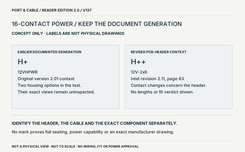
Original 12VHPWR and revised 12V-2x6 are separate document contexts; no physical geometry.
Conceptual source-field relationship; not a physical view · Concept only
Not to scale. Technical and rights review pending.
Inspect view & provenance ↗ (private workspace)
(private workspace)
P193 / Concept — not physical geometry
12VHPWR
Historical Intel ATX 3.0 description
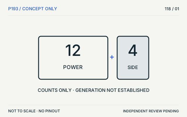
12 power + 4 sideband; not a mating face · Concept only
Not to scale. Technical and rights review pending.
Inspect view & provenance ↗ (private workspace)
Matching notes / PC power / P193
Can contact count identify the GPU-power revision?
FIELD NOTES 03
No. A 12-power-plus-4-sideband description alone does not identify revision-specific physical geometry or a particular cable’s rating.
SOURCE-SUPPORTED LEAD
What the evidence supports
The historical Intel description supports the 12VHPWR contact-group concept.
INSUFFICIENT MATCHING EVIDENCE
What not to conclude
The same total contact count is insufficient evidence for identifying a 12V-2x6 header.
NOT ESTABLISHED
Keep this check open
Exact revision, contact lengths, cable suitability and installation status remain unknown.
Before you choose a part
Read the exact header or equipment designation.
Use the revision-specific manufacturer drawing and installation guide.
Stop if the physical revision or approved cable is unresolved.
Evidence for this decision · 3 source-scoped observations
C193A (private workspace) — Intel describes the 12VHPWR auxiliary-power connector form as twelve larger power contacts plus four smaller sideband contacts and distinguishes it from legacy 2x3/2x4 PCIe forms.
V36 catalogue-expansion identification fact only; not independent technical approval, fabrication data, wiring instruction or end-to-end compatibility proof. S199
C193B (private workspace) — Intel ATX Version 3.0 documents 12VHPWR with twelve larger power contacts plus four smaller sideband contacts, 3.0 mm power-contact spacing, pins 1–6 +12V3/V4, pins 7–12 COM, and sideband S1 CARD_PWR_STABLE, S2 CARD_CBL_PRES#, S3 SENSE0, S4 SENSE1.
V37 engineering-depth sidecar fact; source-checked but not independently human-approved, not a fabrication drawing, and not a safe-substitution or repair instruction. This claim is explicitly historical 12VHPWR/ATX 3.0 scope and is not a 12V-2x6 equivalence claim. S216
C260A (private workspace) — Molex identifies part 2191161161 as a PCIe CEM5 12V-2x6 header with 16 circuits, configured as 12 power and 4 signal circuits.
V43 catalogue-expansion identification fact only; not independent technical approval, fabrication data, wiring instruction, protocol guarantee or end-to-end compatibility proof. S280
Manufacturer evidence is not an independent review, wiring assignment or hardware test.
Visual atlas / Series 02 / P193
Keep the unknown visible.
PHYSICAL VIEW BLOCKED
Contact-count concept. Historical Intel ATX 3.0 description. 12 power + 4 sideband; not a mating face. Independently fitted; not a size reference.
What this view supports
The text separates twelve power contacts from four sideband contacts
Contact counts do not identify a revision-specific header
What remains unknown
This diagram establishes neither pin position nor generation-specific contact lengths or a safe power rating.
Why no physical view? No inspected revision-specific physical view sufficient to depict distinguishing contact geometry.
The next useful check
Find the exact device/header designation and source drawing, then use the equipment installation instructions.
Visual inspection 2026-10-11. AI-assisted source inspection; independent drawing and rights reviews pending. These are original qualitative interpretations, not mechanical drawings, pinouts or approved connections.
Independent simplified vector interpretation and original factual paraphrase only. No manufacturer image, PDF, CAD, logo or traced path is redistributed. Independent technical and rights assessment remains pending.
Identifies legacy 2x3 and 2x4 PCIe auxiliary-power forms and the 12VHPWR form with twelve larger power contacts plus four smaller sideband contacts. Identification/reference scope only. V36 does not convert this source into a universal pinout, fabrication drawing, electrical approval or end-to-end compatibility verdict.
Tables 5-4, 5-5 and 5-7; 12VHPWR connector description
Engineering-sidecar source for legacy PCIe 2x3/2x4 assignments and the ATX 3.0 12VHPWR 12+4 assignment/3.0 mm power-contact spacing context. Exact ATX 3.0 design-guide scope only. 12VHPWR is retained as the documented historical form and must not be silently generalized to later 12V-2x6 revisions or proprietary modular-PSU connectors.
Canonical evidence is retained separately. Existing claim dates are unchanged; only new V118 claims have a new inspection date. No live electrical, energized probing, forced mating or optical-port inspection is recommended.
INTERNAL SYSTEMS / POWER
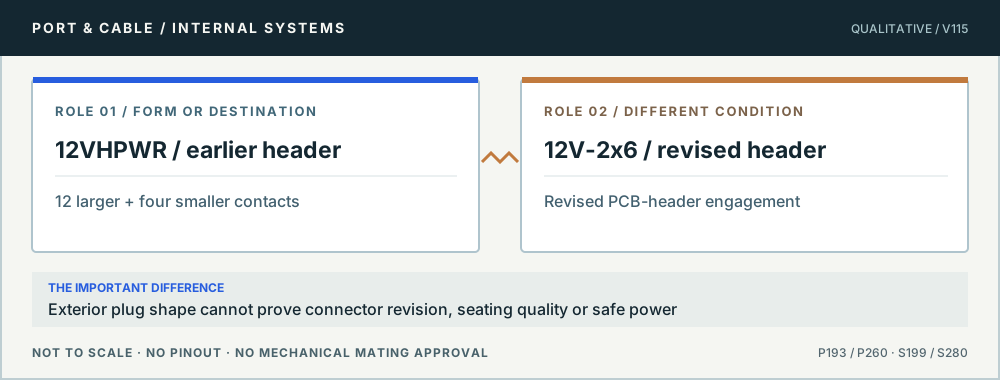
12VHPWR and 12V-2x6: similar mating family, different revision
No. The inherited ATX 3.0 source documents the earlier twelve-power-plus-four-sideband 12VHPWR design. The later Intel ATX 3 (2.1a) revision explicitly replaces the PCB-header definition with 12V-2x6 while retaining a compatible cable-plug interface. Identify the actual hardware revision and full cable/PSU path instead of deciding by the number of visible contacts.
Older vs revised 12+4 power. Original qualitative role diagram; not mechanical artwork, not to scale or a wiring map. Source context S199 · S280.
Three checks before proceeding
Locate the connector revision in GPU, PSU and cable documentation.
Use a known compatible manufacturer cable assembly; never repin or force.
Inspect for damage under equipment-maker procedures and discontinue use if abnormalities are found.
One mistake to avoid
Assuming that a visually similar, possibly partially seated or damaged cable is validated by interchangeability of the nominal plug form.
Claim-specific evidence remains in the canonical record. Concept diagrams do not show any safe wiring or mechanical mating geometry.
The useful distinction
Recognize it. Then verify it.
12VHPWR is a 16-contact auxiliary-power form with twelve larger power contacts and four smaller sideband contacts in the cited ATX guide. [C193A]
Intel revision 2.11 identifies H+ with the previously defined 12VHPWR connector and distinguishes the revised 12V-2x6 PCB connector with H++. [C193C]
Intel version 2.01 describes two original 12VHPWR housing options differentiated by sideband-contact protection. [C193D]
Source-scoped identification facts
Each value retains its exact example, role and measurement axis. Facts from different parts must not be combined into an invented component.
Documented examples; not a mating drawing or compatibility approval
Nominal contacts
16S199Source-backed total of twelve larger plus four smaller contacts; not a pin assignment.
Contact pitch
3 mm Power-contact spacingS216Recorded source-scoped values; named examples do not describe every family variant or establish compatibility. nominal_identifier; ATX 3.0 PCIe auxiliary-power cable plug / add-in-card header interface
Connector role
plug; header; PCB headerS199 · S216 · S561Named source examples retain separate role, part, view and axis limits; values are not a universal family specification. ATX 3.0 PCIe auxiliary-power cable plug / add-in-card header interface IntelATX12VO613768Rev2.11 historical12VHPWR distinction. Documented role: PCB header. This isanexplicitcomparisonofolder12VHPWRandreplacement12V-2x6;H++isnottransferredto12VHPWR.; Noindividualspecimen,600Wcapability,markinglocationorunchangedheaderdimensionsclaimed. Existingdatedvariantsstayseparate.
Series
IntelATX12VO613768Rev2.11 historical12VHPWR distinctionS561Named source examples retain separate role, part, view and axis limits; values are not a universal family specification. IntelATX12VO613768Rev2.11 historical12VHPWR distinction. Documented role: PCB header. This isanexplicitcomparisonofolder12VHPWRandreplacement12V-2x6;H++isnottransferredto12VHPWR.; Noindividualspecimen,600Wcapability,markinglocationorunchangedheaderdimensionsclaimed. Existingdatedvariantsstayseparate.
Recorded markings
Historical12VHPWR PCBconnector is documented with H+;replacement12V-2x6 usesH++.S561Named source examples retain separate role, part, view and axis limits; values are not a universal family specification. IntelATX12VO613768Rev2.11 historical12VHPWR distinction. Documented role: PCB header. This isanexplicitcomparisonofolder12VHPWRandreplacement12V-2x6;H++isnottransferredto12VHPWR.; Noindividualspecimen,600Wcapability,markinglocationorunchangedheaderdimensionsclaimed. Existingdatedvariantsstayseparate.
This is the ATX 3.0 12VHPWR form, not a blanket statement about 12V-2x6 or later revisions.
No physical face orientation, insertion-depth measurement or cable-bend guidance is inferred here.
Use current PSU/GPU manufacturer documentation for an actual installation.
12VHPWR cable plug, per Intel's statement that the renamed 12V-2x6 cable plug is unchanged: Identifiers per Table 5-7.
GIGABYTE GP-UD850GM-A PG5 'PCI-E 16 Pin' cable: Drawing on the cited page.
Intel guide rev 2.0 12VHPWR: Intel Figure 5-4 cable-plug assembly face drawing, sideband below: pin 1 lower left, pin 2 immediately right of it, pin 12 upper right; S1 left, S4 right. Not a PCB-header or cable wire-entry view.
Retained rows context (excluded from normalized contact/body field): 2. V36 catalogue-expansion identification fact only; not independent technical approval, fabrication data, wiring instruction or end-to-end compatibility proof. Sources: S199: PCIe auxiliary power connector section
Retained rows context (excluded from normalized contact/body field): 2. Printed page 63. A label comparison is not an assessment of an actual cable, seating, available power or exact manufacturer part. Sources: S561: Revision 2.11 / May 2024. Printed pages 17, 58, 59 and 63 visually inspected; page 63 special note compares 12V-2x6 and earlier 12VHPWR.
Not included. Check exact device and accessory documentation.
A boundary, not an omission to guess around.
Use the source-backed form or position count only for identification. Resolve ratings, protocol, direction, wiring, cable construction and exact device support from the relevant equipment and component documentation.
Before you connect
What to check
Identify the exact connector family and variant from the equipment or cable documentation.
Keep shape, contact count, protocol, electrical rating and device support as separate facts.
Do not force, rewire or adapt a connector from this recognition record; resolve the remaining requirements first.
Choose the exact wiring. Pin numbers follow its stated view; a schematic does not establish physical positions. Check your exact device before wiring.
What the status labels mean
Confirmed
Recorded research passes agree within this variant; this is not independent human review or hardware validation.
Single source
Only one underlying document, or one pass, supports this assignment.
Device-specific
Supported for the named equipment or wiring only. Check your device’s manual.
Unverified
Missing or conflicting evidence. Do not wire from this row.
Not connected
The source explicitly says NC, no contact or no pin for this wiring.
What is not established
This field note does not approve a connection, adapter, cable assembly, rewiring scheme or fabricated part. It intentionally omits unsupported pin assignments and mechanical tolerances.
AI-assisted inspection is not independent engineering review. Source scope and access limitations are disclosed below. Procedural checklists are editorial requirements, not hardware measurements.
Intel describes the 12VHPWR auxiliary-power connector form as twelve larger power contacts plus four smaller sideband contacts and distinguishes it from legacy 2x3/2x4 PCIe forms.
Locator: PCIe auxiliary power connector section Access: public page. Identification/reference scope only. V36 does not convert this source into a universal pinout, fabrication drawing, electrical approval or end-to-end compatibility verdict.
Locator: Revision 2.11 / May 2024. Printed pages 17, 58, 59 and 63 visually inspected; page 63 special note compares 12V-2x6 and earlier 12VHPWR. Access: public pdf text. No independent review, wiring, current rating, mating or fabrication approval. Retrieval status and document revision retained.
Claim scope: Printed page 63. A label comparison is not an assessment of an actual cable, seating, available power or exact manufacturer part.. Next review due 2027-01-10.
Locator: Version 2.01 / document 336521 / 1 February 2023. Original 12VHPWR subsection: H+ identifier and two housing options distinguished by sideband protection. Access: public page. No independent review, wiring, current rating, mating or fabrication approval. Retrieval status and document revision retained.
Claim scope: Historical text only; neither option’s geometry was visually inspected in this round. A later 12V-2x6 illustration is not substituted.. Next review due 2027-01-10.
Intel ATX12VO Design Guide revision 2.11 — role and generation boundaries ↗ Revision 2.11 / May 2024. Printed pages 17, 58, 59 and 63 visually inspected; page 63 special note compares 12V-2x6 and earlier 12VHPWR. S561 · canonical observation date 2026-10-12. This specified guide revision only. It separates PCB headers from cable plugs and describes changed PCB-header contact lengths. No pinout, dimensions, sensing circuit, power rating or fit approval is imported.
Intel ATX multi-rail guide version 2.01 — original 12VHPWR options ↗ Version 2.01 / document 336521 / 1 February 2023. Original 12VHPWR subsection: H+ identifier and two housing options distinguished by sideband protection. S562 · canonical observation date 2026-10-12. Historical HTML text was available during this session; subsequent refresh attempts timed out. The figures were not visually inspected. No original physical silhouette or current-version assertion is supplied.
Observation date is not a document issue date. No hardware, wiring, seating, fit or independent approval.
No new physical view closes this reference’s image request in V137. Concepts are not specimen substitutes.
Assessment 2026-10-22 · earliest scheduled source review 2027-01-03. This is a recorded-date assessment, not a live source check. Page-level independent review is not established by this panel.
Scoped support: Identifies legacy 2x3 and 2x4 PCIe auxiliary-power forms and the 12VHPWR form with twelve larger power contacts plus four smaller sideband contacts.
Not established / limitations: Identification/reference scope only. V36 does not convert this source into a universal pinout, fabrication drawing, electrical approval or end-to-end compatibility verdict.
Scoped support: This specified guide revision only. It separates PCB headers from cable plugs and describes changed PCB-header contact lengths. No pinout, dimensions, sensing circuit, power rating or fit approval is imported.
Not established / limitations: No independent review, wiring, current rating, mating or fabrication approval. Retrieval status and document revision retained.
Locator: Revision 2.11 / May 2024. Printed pages 17, 58, 59 and 63 visually inspected; page 63 special note compares 12V-2x6 and earlier 12VHPWR.
Scoped support: Historical HTML text was available during this session; subsequent refresh attempts timed out. The figures were not visually inspected. No original physical silhouette or current-version assertion is supplied.
Not established / limitations: No independent review, wiring, current rating, mating or fabrication approval. Retrieval status and document revision retained.
Locator: Version 2.01 / document 336521 / 1 February 2023. Original 12VHPWR subsection: H+ identifier and two housing options distinguished by sideband protection.
Trace 3 claims to their source records
C193A · P193
Intel describes the 12VHPWR auxiliary-power connector form as twelve larger power contacts plus four smaller sideband contacts and distinguishes it from legacy 2x3/2x4 PCIe forms.
Claim scope: V36 catalogue-expansion identification fact only; not independent technical approval, fabrication data, wiring instruction or end-to-end compatibility proof.
Recorded evidence only. An inspection date, publisher label, source link or generated packet is not independent technical review, hardware testing, fabrication approval or a compatibility verdict.

 (private workspace)