FIELD GUIDESource-led reference

Side by side

8-pin CPU power versus 8-pin PCIe auxiliary power

What does the PSU cable and motherboard/GPU manual call this connector? Pin count alone is not enough.

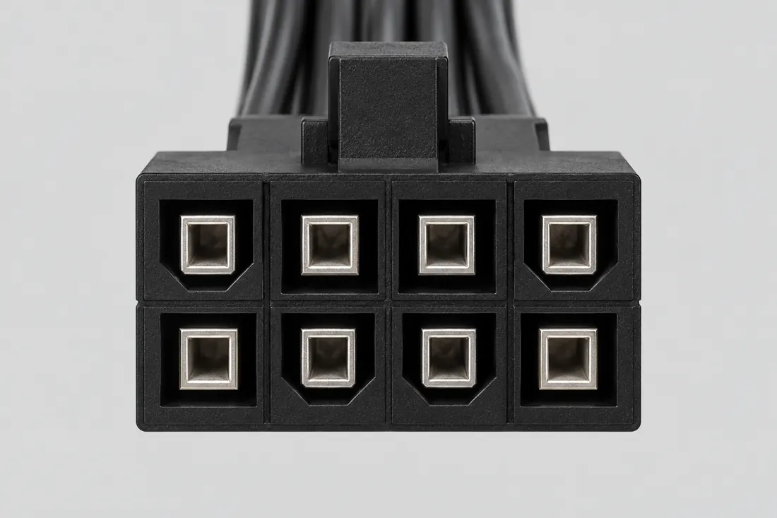
Computer-generated illustration, not a photograph.
P190 · Connector8-pin +12 V CPU power connector (EPS12V form)
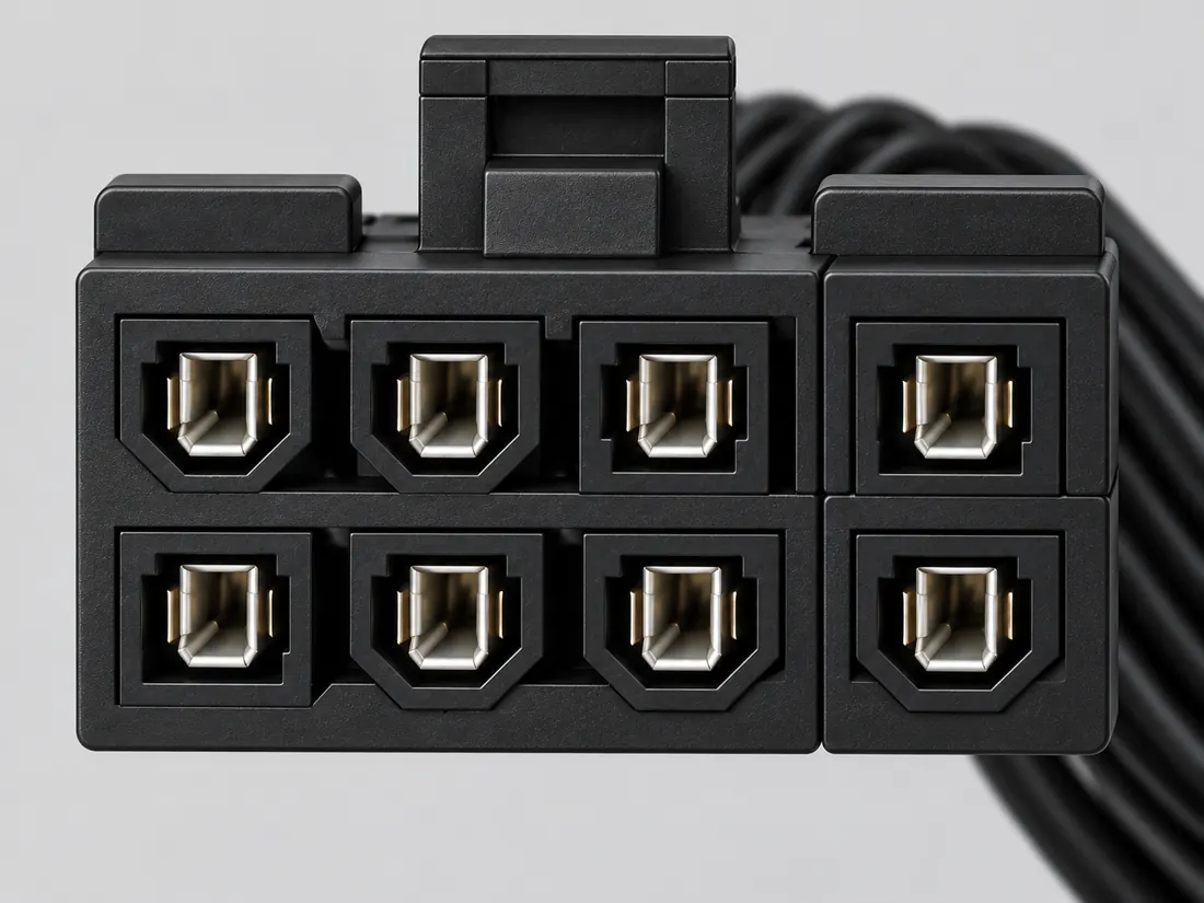
Computer-generated illustration, not a photograph.
P192 · ConnectorPCIe 8-pin auxiliary power connector

How they differ

CPU/EPS and PCIe auxiliary-power families can share a nominal count while serving different documented roles.

  • CORSAIR’s cited EPS cable example uses a different split arrangement from its PCIe example. The split is an example, not a universal recognition rule. S474 · S474
  • A motherboard can have a PCIe-power input as well as processor power; board location does not identify the connector family. S560
  • The board header and cable-plug harness are different objects; do not mirror a logical assignment table into a physical face map. S561

What this comparison does not establish: Check exact modular PSU cable type: incorrect substitutions can damage hardware. S489 · S489

Choose the next check

Match the exact PSU model/cable family with the motherboard or add-in-card connector specified in its manual.

Report a comparison correction →

At a glance

Source-scoped form facts; counts, variants and unknowns are distinct
Field8-pin +12 V CPU power connector (EPS12V form)PCIe 8-pin auxiliary power connector
TypeConnectorConnector
FamilyPC powerPC power
Shapedual rowdual row
Nominal contacts8S198Documented position count only; V36 does not publish the electrical assignment.8S199Documented position count only; no V36 electrical pin map.
Positions / cavity span8 (Claim C190E)S560Recorded source-scoped values; named examples do not describe every family variant or establish compatibility. The documented configurations are examples; connector count alone does not determine an unknown motherboard’s requirements.8 (Claim C192C)S474Recorded source-scoped values; named examples do not describe every family variant or establish compatibility. Do not infer cable role solely from the equipment category or position count.
Contact rows2 (Source-described array; C190A); 2 (Molex39-01-2080)S198 · S977 · S760Current primary-source scoped values; named examples remain separate and unknowns are not inferred from illustrations. V36 catalogue-expansion identification fact only; not independent technical approval, fabrication data, wiring instruction or end-to-end compatibility proof. Exact Molex39-01-2080 receptacle housing named in SSI PSDG2008v1.2.1 section4.2.2, component geometry only. Quantity context: Manufacturer Number of Rows / SSI2x4 array.2 (Source-described array; C192A); 2 (Source-described array; C192B); 2 (Source-described array; C192E)S199 · S216 · S561Recorded source-scoped values; named examples do not describe every family variant or establish compatibility. V36 catalogue-expansion identification fact only; not independent technical approval, fabrication data, wiring instruction or end-to-end compatibility proof. V37 engineering-depth sidecar fact; source-checked but not independently human-approved, not a fabrication drawing, and not a safe-substitution or repair instruction. Printed page 59 only. The guide-specific connection description is not a PSU-side socket assignment or permission to reuse an unknown cable.
Connector roleplug; headerS198 · S215Recorded source-scoped values; named examples do not describe every family variant or establish compatibility. processor-power cable plug / motherboard header interfaceplug; headerS199 · S216Recorded source-scoped values; named examples do not describe every family variant or establish compatibility. PCIe auxiliary-power cable plug / add-in-card header interface
Key distinctionAn eight-position PC power shell can be confused with PCIe auxiliary power; keying and device documentation matter.This eight-position PC power form is not interchangeable with every 8-pin CPU-power connector.

Full evidence ledger and sources ↓

Illustrations are computer-generated with prior AI visual review; independent technical and rights review pending. A comparison is not a compatibility verdict.

This comparison stays within one evidence layer.

All selected records are Connector records. Similar layer does not mean compatible, interchangeable or safe to mate.

Families represented: PC power

T08 · Document the actual path

GPU versus CPU auxiliary power

Do not select a CPU/EPS or GPU/PCIe power cable by count, location or a similar shell. Use the exact PSU/cable type and motherboard/GPU documentation; unresolved cable identity or review scope is a stop.

Read three exact-equipment examples →

What does the exact equipment documentation establish?

Unknown is a useful answer. Yes means you have the relevant model/port/product statement; it does not mean this site verified your equipment.

Read the connector designation in the motherboard or GPU manual. A motherboard may also have a PCIe-power input.

Use the PSU maker’s model/cable compatibility documentation; incorrect modular cable types can damage hardware. Do not trial-fit.

Check the actual part/revision evidence. P260 cable-housing illustrations do not prove the revised header’s contact lengths or marking.

Stop before any power connection.

  • Keep this power path disconnected. Obtain exact manufacturer support and qualified technical review; declarations here do not clear the unresolved review gate.
  • Read the connector designation in the motherboard or GPU manual. A motherboard may also have a PCIe-power input.
  • Use the PSU maker’s model/cable compatibility documentation; incorrect modular cable types can damage hardware. Do not trial-fit.
  • Check the actual part/revision evidence. P260 cable-housing illustrations do not prove the revised header’s contact lengths or marking.

Documentation declarations only; no physical test, negotiated mode, delivered power, safe mating, pinout or compatibility approval. 3 missing prerequisites; 0 recorded conflicts.

Read the scoped power distinction →

No pinout/wiring or installation instructions. Independent qualified technical review remains unresolved in this candidate.

Source scope and original inspection information
  • S280 · Micro-Fit+ PCIe CEM5 12V-2x6 header

    Part details and PCIe CEM5 12V2x6 product specification · Revision not recorded · Recorded source inspection 2026-10-06. Identification/reference scope only. V43 does not convert this source into a universal pinout, fabrication drawing, electrical approval, protocol guarantee or end-to-end compatibility verdict.

  • S474 · Which PSU cables go where? — EPS and PCIe sections

    4-pin ATX12V / 8-pin EPS12V and 6-pin / 6+2-pin PCIe sections. Text inspected; linked product images could not be retrieved. · Revision not recorded · Recorded source inspection 2026-10-11. Only the exact named source/example supports the observation. No universal mating, wiring, maximum rating or mechanical tolerance is inferred. Not identified; retrieval is not a revision date.

  • S489 · PSU cable compatibility — Type 3/4 versus Type 5 warning

    Disclaimer item 3; cable-type headings. The model chart icon cells are not interpreted. · Revision not recorded · Recorded source inspection 2026-10-11. Exact source and example only; no device approval, universal rating, wiring or manufacturing tolerance is inferred. Remote raw-file retention is reported separately.

  • S560 · CORSAIR power-cable guide — required inputs and connector location

    4-pin ATX12V / 8-pin EPS12V and 6-pin / 6+2-pin PCIe sections; accompanying physical images were not visually inspectable. · Revision not recorded · Recorded source inspection 2026-10-12. No independent review, wiring, current rating, mating or fabrication approval. Retrieval status and document revision retained.

  • S561 · Intel ATX12VO Design Guide revision 2.11 — role and generation boundaries

    Revision 2.11 / May 2024. Printed pages 17, 58, 59 and 63 visually inspected; page 63 special note compares 12V-2x6 and earlier 12VHPWR. · Revision not recorded · Recorded source inspection 2026-10-12. No independent review, wiring, current rating, mating or fabrication approval. Retrieval status and document revision retained.

Three exact-equipment examples

These are source-backed documentation cases. They do not select your equipment, fill the form above, or report a hardware test.

T08-S1 · Supported within the stated documentation scope

An EPS cable and the board’s CPU power role

Document the designated Type 4 EPS cable role for this motherboard power input.

motherboard ATX_12V power input
ASUS PRIME B550-PLUS AC-HES — selected storage and PCIe slots M05-29
Type 4 modular PSU
Corsair RM1000x ATX 3.1 (2024) M05-31
Type 4 EPS12V CPU cable
Corsair CP-8920141 M05-30
Keep these conditions
  • The PSU is specifically the2024 RM1000x ATX3.1 version, not another RM1000x revision.
  • This resolves cable role and published PSU family only; full system load, connector condition and installation remain separate.
  • ASUS identifies an8-pin+12V motherboard power input. Corsair identifies CP-8920141 as Type4 EPS12V and the2024 RMx family as Type4 with separate EPS and PCIe cable classes. M05-29 · M05-30 · M05-31

Supported within the stated documentation scope: The documented EPS role and named PSU cable family align for this bounded identification question. A fully powered system has not been assessed or tested.

Next check: Keep the PSU SKU/revision and exact cable identification with the motherboard manual; follow their installation instructions.

Documentation scope only. This is not a hardware test, detected device state, pinout, electrical replacement approval or guarantee for another product/revision.

Exact source scopes and inspection dates
  • M05-29 · PRIME B550-PLUS AC-HES user manual

    PDF p.8 internal power connectors; pp.12-13 section 1.2.1 item5 Power connectors, ATX_12V board label · E18712 first edition July 2021 · Inspected 2026-10-22. Selected exact-model documentation only; no hardware test or broader family approval.

  • M05-31 · RMx ATX 3.1 2024 cable compatibility

    Which cable type; RM1000x cables: Type4, EPS4+4, PCIe6+2 and native12V-2x6 are distinct; compatible cables only · No document revision shown on inspected page · Inspected 2026-10-22. Selected exact-model documentation only; no hardware test or broader family approval.

  • M05-30 · PSU spare parts

    Stock Type 4 cables table: CP-8920141 EPS12V versus CP-8920143 PCIe pigtail; exact PSU pinout type required · No document revision shown on inspected page · Inspected 2026-10-22. Selected exact-model documentation only; no hardware test or broader family approval.

Report a correction to this example →

T08-S2 · The proposed path disagrees with the documentation

PCIe6+2 and EPS4+4 labels are different roles

Treat a Type 4 PCIe pigtail cable as the board’s EPS power cable.

motherboard ATX_12V power input
ASUS PRIME B550-PLUS AC-HES — selected storage and PCIe slots M05-29
Type 4 modular PSU
Corsair RM1000x ATX 3.1 (2024) M05-31
Type 4 PCIe pigtail cable
Corsair CP-8920143 M05-30
Keep these conditions
  • The candidate is CP-8920143, not CP-8920141.
  • Corsair lists CP-8920143 as PCIe and CP-8920141 as EPS12V; the RM1000x documentation keeps EPS4+4 and PCIe6+2 cable classes separate. M05-30 · M05-31
  • The ASUS board identifies its motherboard+12V power connector separately from expansion-card interfaces. M05-29

The proposed path disagrees with the documentation: The proposed cable’s documented role disagrees with the motherboard power role. A shared eight-contact total is not interchangeability evidence.

Next check: Use the exact PSU and component documentation to identify the designated cable; do not force or repin a cable from an outline comparison.

Documentation scope only. This is not a hardware test, detected device state, pinout, electrical replacement approval or guarantee for another product/revision.

Exact source scopes and inspection dates
  • M05-29 · PRIME B550-PLUS AC-HES user manual

    PDF p.8 internal power connectors; pp.12-13 section 1.2.1 item5 Power connectors, ATX_12V board label · E18712 first edition July 2021 · Inspected 2026-10-22. Selected exact-model documentation only; no hardware test or broader family approval.

  • M05-31 · RMx ATX 3.1 2024 cable compatibility

    Which cable type; RM1000x cables: Type4, EPS4+4, PCIe6+2 and native12V-2x6 are distinct; compatible cables only · No document revision shown on inspected page · Inspected 2026-10-22. Selected exact-model documentation only; no hardware test or broader family approval.

  • M05-30 · PSU spare parts

    Stock Type 4 cables table: CP-8920141 EPS12V versus CP-8920143 PCIe pigtail; exact PSU pinout type required · No document revision shown on inspected page · Inspected 2026-10-22. Selected exact-model documentation only; no hardware test or broader family approval.

Report a correction to this example →

T08-S3 · Specific information is still missing

A named cable still needs the exact PSU model

Decide whether a loose CP-8920141 cable belongs to an unidentified modular PSU.

motherboard ATX_12V power input
ASUS PRIME B550-PLUS AC-HES — selected storage and PCIe slots M05-29
Type 4 EPS12V CPU cable
Corsair CP-8920141 M05-30
Keep these conditions
  • The cable and motherboard are named; the PSU maker, SKU and revision are missing.
  • Corsair scopes CP-8920141 to its Type4 pinout PSUs; the2024 RMx article requires compatible cables and distinguishes them from other types. M05-30 · M05-31

Specific information is still missing: The motherboard end does not determine the PSU-side pinout. Without the actual PSU identity, the cable-family match remains unresolved.

Still needed:

  • PSU maker, model/SKU and revision
  • Manufacturer-confirmed PSU-side cable family

Next check: Identify the PSU label and consult its maker’s exact cable compatibility record before considering any connection.

Documentation scope only. This is not a hardware test, detected device state, pinout, electrical replacement approval or guarantee for another product/revision.

Exact source scopes and inspection dates
  • M05-29 · PRIME B550-PLUS AC-HES user manual

    PDF p.8 internal power connectors; pp.12-13 section 1.2.1 item5 Power connectors, ATX_12V board label · E18712 first edition July 2021 · Inspected 2026-10-22. Selected exact-model documentation only; no hardware test or broader family approval.

  • M05-30 · PSU spare parts

    Stock Type 4 cables table: CP-8920141 EPS12V versus CP-8920143 PCIe pigtail; exact PSU pinout type required · No document revision shown on inspected page · Inspected 2026-10-22. Selected exact-model documentation only; no hardware test or broader family approval.

  • M05-31 · RMx ATX 3.1 2024 cable compatibility

    Which cable type; RM1000x cables: Type4, EPS4+4, PCIe6+2 and native12V-2x6 are distinct; compatible cables only · No document revision shown on inspected page · Inspected 2026-10-22. Selected exact-model documentation only; no hardware test or broader family approval.

Report a correction to this example →
Report a correction to this task →

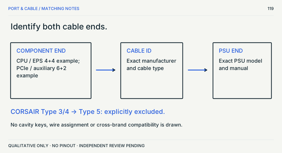
Matching diagram / concept only

Identify both cable ends.

Component role does not settle modular PSU compatibility.

Separate CPU/PCIe component roles and exact PSU cable-type check. No cavity geometry.
Component role does not settle modular PSU compatibility. Concept diagram, not physical geometry or a connection approval.

Not a hardware compatibility verdict. S198 · S474 · S489 · S199

The reference ledger

Read the same question across.

2 selected records · 13 fields
No score. No compatibility verdict.

On a narrow screen, scroll the table sideways or open the field-by-field reading view below. Illustrations are not a size comparison.

Comparison of selected field notes; source links accompany each documented specification
What you are comparing
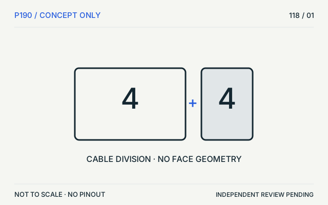
EPS12V / CPU: Two equally sized labelled groups: 4 + 4. Concept diagram only; no physical connector geometry is depicted.
P190 / Connector8-pin +12 V CPU power connector (EPS12V form)

Identification schematic · not to scale · drawing review pending

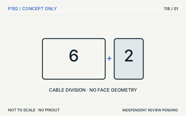
PCIe / auxiliary: A larger group of 6 beside a smaller group of 2. Concept diagram only; no physical connector geometry is depicted.
P192 / ConnectorPCIe 8-pin auxiliary power connector

Identification schematic · not to scale · drawing review pending

LayerConnectorConnector
Key distinctionAn eight-position PC power shell can be confused with PCIe auxiliary power; keying and device documentation matter.This eight-position PC power form is not interchangeable with every 8-pin CPU-power connector.
Nominal contacts8S198Documented position count only; V36 does not publish the electrical assignment.8S199Documented position count only; no V36 electrical pin map.
Positions / cavity span8 (Claim C190E)S560Recorded source-scoped values; named examples do not describe every family variant or establish compatibility. The documented configurations are examples; connector count alone does not determine an unknown motherboard’s requirements.8 (Claim C192C)S474Recorded source-scoped values; named examples do not describe every family variant or establish compatibility. Do not infer cable role solely from the equipment category or position count.
Populated contactsNot recordedNot recorded in a normalized source-scoped field. Consult the exact part/revision; no value inferred from illustrations.Not recordedNot recorded in a normalized source-scoped field. Consult the exact part/revision; no value inferred from illustrations.
Contact rows2 (Source-described array; C190A); 2 (Molex39-01-2080)S198 · S977 · S760Current primary-source scoped values; named examples remain separate and unknowns are not inferred from illustrations. V36 catalogue-expansion identification fact only; not independent technical approval, fabrication data, wiring instruction or end-to-end compatibility proof. Exact Molex39-01-2080 receptacle housing named in SSI PSDG2008v1.2.1 section4.2.2, component geometry only. Quantity context: Manufacturer Number of Rows / SSI2x4 array.2 (Source-described array; C192A); 2 (Source-described array; C192B); 2 (Source-described array; C192E)S199 · S216 · S561Recorded source-scoped values; named examples do not describe every family variant or establish compatibility. V36 catalogue-expansion identification fact only; not independent technical approval, fabrication data, wiring instruction or end-to-end compatibility proof. V37 engineering-depth sidecar fact; source-checked but not independently human-approved, not a fabrication drawing, and not a safe-substitution or repair instruction. Printed page 59 only. The guide-specific connection description is not a PSU-side socket assignment or permission to reuse an unknown cable.
Contact pitch4.2 mm Manufacturer Pitch Mating Interface (Molex39-01-2080)S977 · S760Current primary-source scoped values; named examples remain separate and unknowns are not inferred from illustrations. Exact Molex39-01-2080 receptacle housing named in SSI PSDG2008v1.2.1 section4.2.2, component geometry only.4.2 mm manufacturer-reported centerline or mating-interface pitch (NVIDIA GRID K2 eight-pin PCIe power header)S765Separate exact examples; retain each value’s source, role, axis and part scope. Exact named example NVIDIA GRID K2 eight-pin PCIe power header: Device-specific board header. Exact example only; no universal geometry, electrical compatibility, fabrication approval or wiring instruction. Named2013board example only. Do not treat as every modernGPUheader geometry or modularPSU pinout.
Dimensions / axisNot recordedNot recorded in a normalized source-scoped field. Consult the exact part/revision; no value inferred from illustrations.18 ± 0.25 mm housing width (NVIDIA GRID K2 eight-pin PCIe power header); 11.4 ± 0.25 mm housing height (NVIDIA GRID K2 eight-pin PCIe power header); 18.1 ± 0.25 mm front-to-rear overall connector extent including formed PCB tails (NVIDIA GRID K2 eight-pin PCIe power header)S765Separate exact examples; retain each value’s source, role, axis and part scope. Exact named example NVIDIA GRID K2 eight-pin PCIe power header: Device-specific board header. Exact example only; no universal geometry, electrical compatibility, fabrication approval or wiring instruction. Named2013board example only. Do not treat as every modernGPUheader geometry or modularPSU pinout.
Connector roleplug; headerS198 · S215Recorded source-scoped values; named examples do not describe every family variant or establish compatibility. processor-power cable plug / motherboard header interfaceplug; headerS199 · S216Recorded source-scoped values; named examples do not describe every family variant or establish compatibility. PCIe auxiliary-power cable plug / add-in-card header interface
Coupling / latchNot recordedNot recorded in a normalized source-scoped field. Consult the exact part/revision; no value inferred from illustrations.Not recordedNot recorded in a normalized source-scoped field. Consult the exact part/revision; no value inferred from illustrations.
Keying / polarizationsquare and chamfered cavities shown with latch above; exact pattern belongs to this board drawing, not a universal EPS/PCIe interchange rule (MSI B550-A PRO CPU_PWR1)S757Separate exact examples; retain each value’s source, role, axis and part scope. Exact named example MSI B550-A PRO CPU_PWR1: Device-specific eight-position CPU power header. Exact example only; no universal geometry, electrical compatibility, fabrication approval or wiring instruction. MSI is board vendor; connector OEM/series/pitch remain unknown. Do not import unrelated Molex8-position housing as an EPS equivalent.position1indicator and alignment rib shown in Figure7 (NVIDIA GRID K2 eight-pin PCIe power header)S765Separate exact examples; retain each value’s source, role, axis and part scope. Exact named example NVIDIA GRID K2 eight-pin PCIe power header: Device-specific board header. Exact example only; no universal geometry, electrical compatibility, fabrication approval or wiring instruction. Named2013board example only. Do not treat as every modernGPUheader geometry or modularPSU pinout.
Documented identification8-position 2x4 +12 V processor-power form.C190A8-position 2x4 PCIe auxiliary-power form.C192A
EvidenceC190A,C190C,C190D,C190E,C190W →
Independent review pending
C192A,C192C,C192D,C192E,C192F →
Independent review pending
Read field by field — no sideways scrolling

The same selected records, fields, values and source links as the table. Missing fields remain non-equivalent; no values are merged.

Layer

PCIe 8-pin auxiliary power connectorP192 / Connector
Connector

Key distinction

8-pin +12 V CPU power connector (EPS12V form)P190 / Connector
An eight-position PC power shell can be confused with PCIe auxiliary power; keying and device documentation matter.
PCIe 8-pin auxiliary power connectorP192 / Connector
This eight-position PC power form is not interchangeable with every 8-pin CPU-power connector.

Nominal contacts

8-pin +12 V CPU power connector (EPS12V form)P190 / Connector
8S198Documented position count only; V36 does not publish the electrical assignment.
PCIe 8-pin auxiliary power connectorP192 / Connector
8S199Documented position count only; no V36 electrical pin map.

Positions / cavity span

8-pin +12 V CPU power connector (EPS12V form)P190 / Connector
8 (Claim C190E)S560Recorded source-scoped values; named examples do not describe every family variant or establish compatibility. The documented configurations are examples; connector count alone does not determine an unknown motherboard’s requirements.
PCIe 8-pin auxiliary power connectorP192 / Connector
8 (Claim C192C)S474Recorded source-scoped values; named examples do not describe every family variant or establish compatibility. Do not infer cable role solely from the equipment category or position count.

Populated contacts

8-pin +12 V CPU power connector (EPS12V form)P190 / Connector
Not recordedNot recorded in a normalized source-scoped field. Consult the exact part/revision; no value inferred from illustrations.
PCIe 8-pin auxiliary power connectorP192 / Connector
Not recordedNot recorded in a normalized source-scoped field. Consult the exact part/revision; no value inferred from illustrations.

Contact rows

8-pin +12 V CPU power connector (EPS12V form)P190 / Connector
2 (Source-described array; C190A); 2 (Molex39-01-2080)S198 · S977 · S760Current primary-source scoped values; named examples remain separate and unknowns are not inferred from illustrations. V36 catalogue-expansion identification fact only; not independent technical approval, fabrication data, wiring instruction or end-to-end compatibility proof. Exact Molex39-01-2080 receptacle housing named in SSI PSDG2008v1.2.1 section4.2.2, component geometry only. Quantity context: Manufacturer Number of Rows / SSI2x4 array.
PCIe 8-pin auxiliary power connectorP192 / Connector
2 (Source-described array; C192A); 2 (Source-described array; C192B); 2 (Source-described array; C192E)S199 · S216 · S561Recorded source-scoped values; named examples do not describe every family variant or establish compatibility. V36 catalogue-expansion identification fact only; not independent technical approval, fabrication data, wiring instruction or end-to-end compatibility proof. V37 engineering-depth sidecar fact; source-checked but not independently human-approved, not a fabrication drawing, and not a safe-substitution or repair instruction. Printed page 59 only. The guide-specific connection description is not a PSU-side socket assignment or permission to reuse an unknown cable.

Contact pitch

8-pin +12 V CPU power connector (EPS12V form)P190 / Connector
4.2 mm Manufacturer Pitch Mating Interface (Molex39-01-2080)S977 · S760Current primary-source scoped values; named examples remain separate and unknowns are not inferred from illustrations. Exact Molex39-01-2080 receptacle housing named in SSI PSDG2008v1.2.1 section4.2.2, component geometry only.
PCIe 8-pin auxiliary power connectorP192 / Connector
4.2 mm manufacturer-reported centerline or mating-interface pitch (NVIDIA GRID K2 eight-pin PCIe power header)S765Separate exact examples; retain each value’s source, role, axis and part scope. Exact named example NVIDIA GRID K2 eight-pin PCIe power header: Device-specific board header. Exact example only; no universal geometry, electrical compatibility, fabrication approval or wiring instruction. Named2013board example only. Do not treat as every modernGPUheader geometry or modularPSU pinout.

Dimensions / axis

8-pin +12 V CPU power connector (EPS12V form)P190 / Connector
Not recordedNot recorded in a normalized source-scoped field. Consult the exact part/revision; no value inferred from illustrations.
PCIe 8-pin auxiliary power connectorP192 / Connector
18 ± 0.25 mm housing width (NVIDIA GRID K2 eight-pin PCIe power header); 11.4 ± 0.25 mm housing height (NVIDIA GRID K2 eight-pin PCIe power header); 18.1 ± 0.25 mm front-to-rear overall connector extent including formed PCB tails (NVIDIA GRID K2 eight-pin PCIe power header)S765Separate exact examples; retain each value’s source, role, axis and part scope. Exact named example NVIDIA GRID K2 eight-pin PCIe power header: Device-specific board header. Exact example only; no universal geometry, electrical compatibility, fabrication approval or wiring instruction. Named2013board example only. Do not treat as every modernGPUheader geometry or modularPSU pinout.

Connector role

8-pin +12 V CPU power connector (EPS12V form)P190 / Connector
plug; headerS198 · S215Recorded source-scoped values; named examples do not describe every family variant or establish compatibility. processor-power cable plug / motherboard header interface
PCIe 8-pin auxiliary power connectorP192 / Connector
plug; headerS199 · S216Recorded source-scoped values; named examples do not describe every family variant or establish compatibility. PCIe auxiliary-power cable plug / add-in-card header interface

Coupling / latch

8-pin +12 V CPU power connector (EPS12V form)P190 / Connector
Not recordedNot recorded in a normalized source-scoped field. Consult the exact part/revision; no value inferred from illustrations.
PCIe 8-pin auxiliary power connectorP192 / Connector
Not recordedNot recorded in a normalized source-scoped field. Consult the exact part/revision; no value inferred from illustrations.

Keying / polarization

8-pin +12 V CPU power connector (EPS12V form)P190 / Connector
square and chamfered cavities shown with latch above; exact pattern belongs to this board drawing, not a universal EPS/PCIe interchange rule (MSI B550-A PRO CPU_PWR1)S757Separate exact examples; retain each value’s source, role, axis and part scope. Exact named example MSI B550-A PRO CPU_PWR1: Device-specific eight-position CPU power header. Exact example only; no universal geometry, electrical compatibility, fabrication approval or wiring instruction. MSI is board vendor; connector OEM/series/pitch remain unknown. Do not import unrelated Molex8-position housing as an EPS equivalent.
PCIe 8-pin auxiliary power connectorP192 / Connector
position1indicator and alignment rib shown in Figure7 (NVIDIA GRID K2 eight-pin PCIe power header)S765Separate exact examples; retain each value’s source, role, axis and part scope. Exact named example NVIDIA GRID K2 eight-pin PCIe power header: Device-specific board header. Exact example only; no universal geometry, electrical compatibility, fabrication approval or wiring instruction. Named2013board example only. Do not treat as every modernGPUheader geometry or modularPSU pinout.

Documented identification

8-pin +12 V CPU power connector (EPS12V form)P190 / Connector
8-position 2x4 +12 V processor-power form.C190A
PCIe 8-pin auxiliary power connectorP192 / Connector
8-position 2x4 PCIe auxiliary-power form.C192A

Evidence

Your next step

Use the distinction in context.

Continue the distinction

Compare next

Browse every comparison →

Adjust this comparison

Evidence behind this page

Scope first. Source second. Approval separate.

8 linked sources · 10 scoped claims · 0 sources with inspection/access flags.

Page scope: Evidence behind the compared records; the editorial comparison still needs separate review.

Assessment 2026-10-22 · earliest scheduled source review 2027-01-03. This is a recorded-date assessment, not a live source check. Page-level independent review is not established by this panel.

Inspect 8 source scopes, access limits and dates

S198 · ATX Version 3.0 — +12 V Power Connector

Intel · Manufacturer / product-owner domain · inspected 2026-10-05 · due 2027-01-03

Within inspection window

Scoped support: Documents 4-pin and 8-pin +12 V processor power connector forms; V36 uses only the 8-pin form for identification.

Not established / limitations: Identification/reference scope only. V36 does not convert this source into a universal pinout, fabrication drawing, electrical approval or end-to-end compatibility verdict.

Locator: +12 V CPU power connector section

S199 · ATX Version 3.0 — PCI Express add-in card connectors

Intel · Manufacturer / product-owner domain · inspected 2026-10-05 · due 2027-01-03

Within inspection window

Scoped support: Identifies legacy 2x3 and 2x4 PCIe auxiliary-power forms and the 12VHPWR form with twelve larger power contacts plus four smaller sideband contacts.

Not established / limitations: Identification/reference scope only. V36 does not convert this source into a universal pinout, fabrication drawing, electrical approval or end-to-end compatibility verdict.

Locator: PCIe auxiliary power connector section

S474 · Which PSU cables go where? — EPS and PCIe sections

CORSAIR · Unclassified publisher domain · inspected 2026-10-11 · due 2027-01-09

Within inspection window

Scoped support: Split-cable examples and CPU/PCIe role distinction only. No physical mating-face art is authorized by this text inspection.

Not established / limitations: Only the exact named source/example supports the observation. No universal mating, wiring, maximum rating or mechanical tolerance is inferred. Not identified; retrieval is not a revision date.

Locator: 4-pin ATX12V / 8-pin EPS12V and 6-pin / 6+2-pin PCIe sections. Text inspected; linked product images could not be retrieved.

S489 · PSU cable compatibility — Type 3/4 versus Type 5 warning

CORSAIR · Unclassified publisher domain · inspected 2026-10-11 · due 2027-01-09

Within inspection window

Scoped support: CORSAIR modular PSU cable types only; not cross-brand compatibility.

Not established / limitations: Exact source and example only; no device approval, universal rating, wiring or manufacturing tolerance is inferred. Remote raw-file retention is reported separately.

Locator: Disclaimer item 3; cable-type headings. The model chart icon cells are not interpreted.

S560 · CORSAIR power-cable guide — required inputs and connector location

CORSAIR · Unclassified publisher domain · inspected 2026-10-12 · due 2027-01-10

Within inspection window

Scoped support: Equipment-side roles and the instruction to consult the motherboard manual. The article includes motherboard PCIe-power examples. Its images do not qualify as inspected physical specimens here.

Not established / limitations: No independent review, wiring, current rating, mating or fabrication approval. Retrieval status and document revision retained.

Locator: 4-pin ATX12V / 8-pin EPS12V and 6-pin / 6+2-pin PCIe sections; accompanying physical images were not visually inspectable.

S561 · Intel ATX12VO Design Guide revision 2.11 — role and generation boundaries

Intel · Manufacturer / product-owner domain · inspected 2026-10-12 · due 2027-01-10

Within inspection window

Scoped support: This specified guide revision only. It separates PCB headers from cable plugs and describes changed PCB-header contact lengths. No pinout, dimensions, sensing circuit, power rating or fit approval is imported.

Not established / limitations: No independent review, wiring, current rating, mating or fabrication approval. Retrieval status and document revision retained.

Locator: Revision 2.11 / May 2024. Printed pages 17, 58, 59 and 63 visually inspected; page 63 special note compares 12V-2x6 and earlier 12VHPWR.

S760 · Power Supply Design Guideline for 2008 Dual-Socket Servers and Workstations (A Server System Infrastructure Specification)

SSI Forum (archive hosted by SNIA) · Standards-organization domain · inspected 2026-10-20 · due 2027-01-18

Within inspection window

Scoped support: Exact named pinout variant only; not capability or compatibility approval.

Not established / limitations: Source scope and unresolved evidence are preserved in the engineering variant.

Locator: Section 4.2.1, Table 3 P1 Baseboard Power Connector, printed p. 10; Section 4.2.2, Table 4 Processor 0 / memory power Connector, printed p. 12; Section 4.2.2, Table 5 Processor 1 / memory power Connector, printed p. 12; Section 4.2.4, Table 7 Peripheral Power Connectors (Amp 1-480424-0), printed p. 13; Section 4.2.5, Table 8 Floppy Power Connector (Amp 171822-4), printed p. 13; Section 4.2.8, Table 11 PCI Express Graphic Card Power Connector(s), printed p. 15

S977 · Molex39-01-2080/39012080 receptacle housing physical specifications

Molex · Manufacturer / product-owner domain · inspected 2026-10-22 · due 2027-01-20

Within inspection window

Scoped support: Exact housing binding to SSI processor/memory power connectors.

Not established / limitations: Empty housing is not assembled EPS harness. No loaded contacts, cable wiring, PSU-side shape, generic Mini-Fit key pattern or power compatibility established; live page says Limited Information Available.

Locator: Physical Specifications: Number Of Rows2; Pitch Mating Interface4.20mm; Keywords39-01-2080/0039012080. SSI S760 section4.2.2 PDF/printedp12 explicitly names this eight-position housing and2x4 processor/memory connectors; full PDF text and150dpi page pixels inspected.

Trace 10 claims to their source records

C190A · P190

Intel documents an 8-pin / 2x4 +12 V processor-power connector form in the cited ATX design guide.

Claim scope: V36 catalogue-expansion identification fact only; not independent technical approval, fabrication data, wiring instruction or end-to-end compatibility proof.

Source links: S198 · Evidence trail → (private workspace)

C190C · P190

CORSAIR illustrates the CPU-power cable role with an EPS12V 4+4 arrangement; the split is an example, not a requirement for every EPS cable.

Claim scope: Cable-division concept only; exact face geometry was not inspected.

Source links: S474 · Evidence trail → (private workspace)

C190D · P190

CORSAIR warns that Type 3 and Type 4 modular PSU cables are not compatible with Type 5 power supplies.

Claim scope: This separate PSU-end check is not resolved by identifying an EPS12V component-end connector.

Source links: S489 · Evidence trail → (private workspace)

C190E · P190

CORSAIR describes more than one processor-power input arrangement and directs the reader to the motherboard manual to determine whether both eight-position CPU inputs are required.

Claim scope: The documented configurations are examples; connector count alone does not determine an unknown motherboard’s requirements.

Source links: S560 · Evidence trail → (private workspace)

C190W · P190

SSI names Molex 39-01-2080 for its eight-position 2 × 4 processor/memory power connector. The exact Molex housing specification lists two rows and 4.20 mm mating-interface pitch.

Claim scope: Exact Molex39-01-2080 receptacle housing named in SSI PSDG2008v1.2.1 section4.2.2, component geometry only.

Source links: S977 · S760 · Evidence trail → (private workspace)

C192A · P192

Intel documents a 2x4 PCIe add-in-card auxiliary-power connector form in the cited ATX design guide.

Claim scope: V36 catalogue-expansion identification fact only; not independent technical approval, fabrication data, wiring instruction or end-to-end compatibility proof.

Source links: S199 · Evidence trail → (private workspace)

C192C · P192

CORSAIR describes the eight-position PCIe cable end as a 6+2 arrangement and distinguishes it from EPS12V; some motherboards also use PCIe power connectors.

Claim scope: Do not infer cable role solely from the equipment category or position count.

Source links: S474 · Evidence trail → (private workspace)

C192D · P192

CORSAIR warns that using the incorrect modular PSU cable type may damage hardware and requires cable-type verification before installation.

Claim scope: The component-end PCIe role is separate from exact CORSAIR PSU cable compatibility; no cross-brand pinout is inferred.

Source links: S489 · Evidence trail → (private workspace)

C192E · P192

Intel revision 2.11 describes the PCIe 2x4 connection as a board header and a separate cable-plug harness; these are different component roles.

Claim scope: Printed page 59 only. The guide-specific connection description is not a PSU-side socket assignment or permission to reuse an unknown cable.

Source links: S561 · Evidence trail → (private workspace)

C192F · P192

CORSAIR documents PCIe-power inputs on some motherboards as well as graphics cards; mounting on a motherboard does not by itself identify an EPS12V input.

Claim scope: The final clause is an identification inference from the explicit counterexample, not a claim about every motherboard.

Source links: S560 · Evidence trail → (private workspace)

Prepare this page for review → (private workspace)Read the evidence method →

Recorded evidence only. An inspection date, publisher label, source link or generated packet is not independent technical review, hardware testing, fabrication approval or a compatibility verdict.