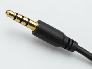
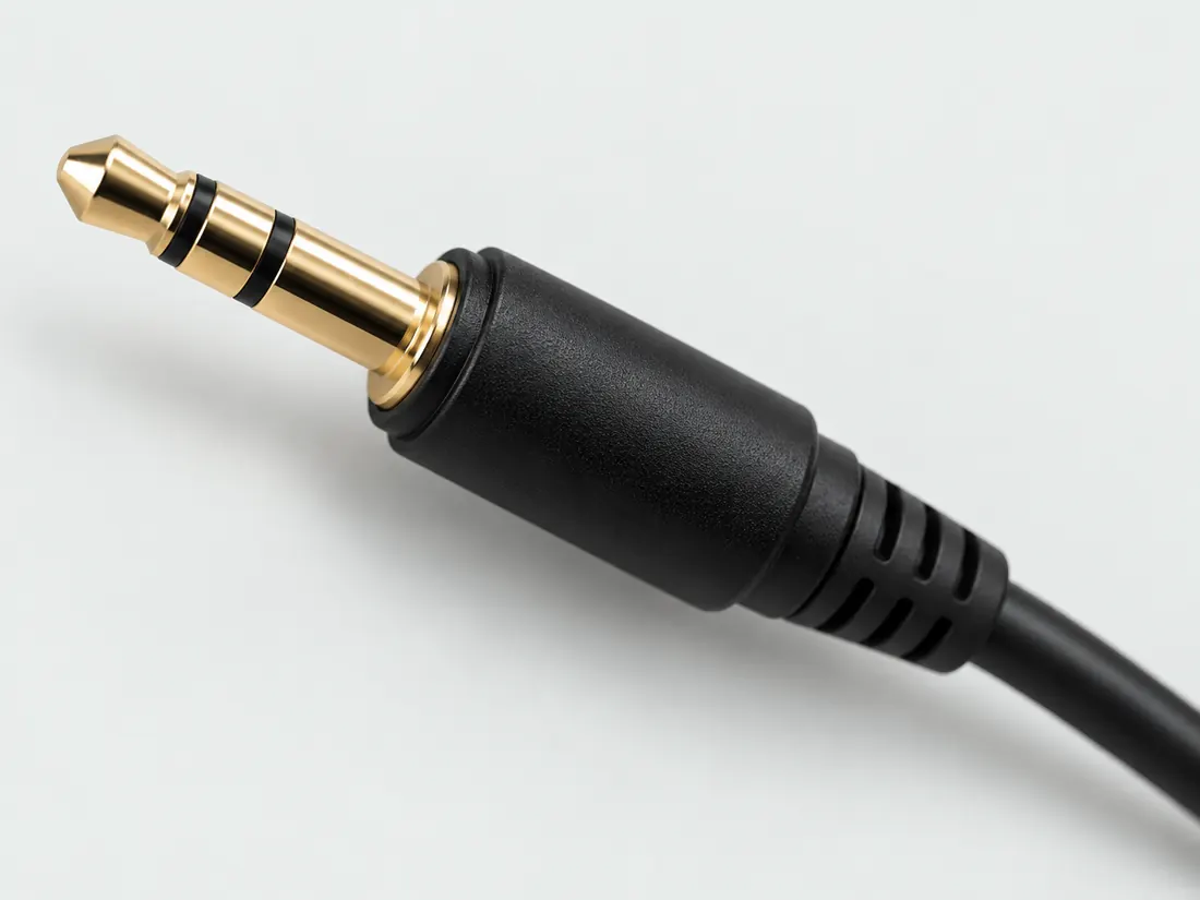
Three-quarter view Computer-generated illustration with prior AI visual review. Not a photograph, measurement or compatibility check. Independent technical and rights review pending.
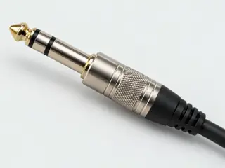
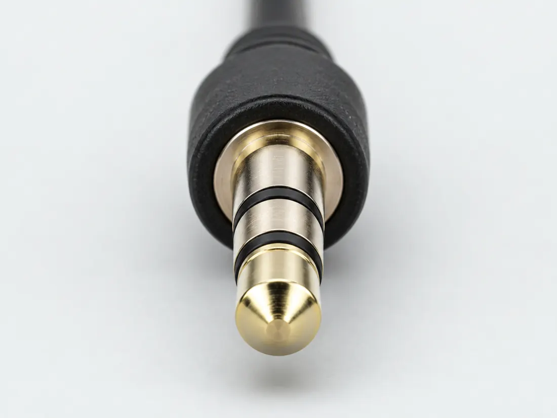
Mating face Computer-generated illustration with prior AI visual review. Not a photograph, measurement or compatibility check. Independent technical and rights review pending.
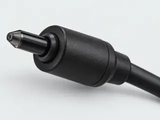
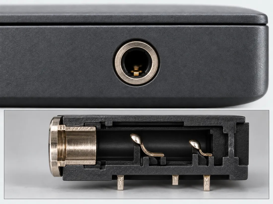
Fitted in place Computer-generated illustration with prior AI visual review. Not a photograph, measurement or compatibility check. Independent technical and rights review pending.
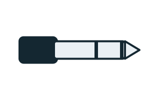
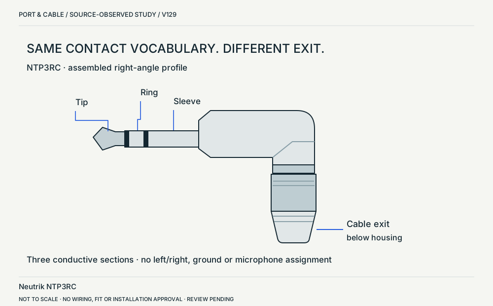
Recognition drawing Original schematic, not to scale. Drawing review pending.
Pins & wiring
Pinout
Choose the exact wiring. Pin numbers follow its stated view; a schematic does not establish physical positions. Check your exact device before wiring.
What the status labels mean
Confirmed
Recorded research passes agree within this variant; this is not independent human review or hardware validation.
Single source
Only one underlying document, or one pass, supports this assignment.
Device-specific
Supported for the named equipment or wiring only. Check your device’s manual.
Unverified
Missing or conflicting evidence. Do not wire from this row.
Not connected
The source explicitly says NC, no contact or no pin for this wiring.
Image inspection / P019
See the view. Check its scope.
2 registered views for this reference. Different part examples are not automatically mates; all remain not to scale and independently unapproved.
(private workspace)
P019 / Source-observed physical study
NTP3RC / right-angle profile
Neutrik NTP3RC
Upper-right side elevation in ST-NTP3RC · Cable plug / cable end
Not to scale. Technical and rights review pending.
Inspect view & provenance ↗ (private workspace)
(private workspace)
P019 / Inherited recognition study
3.5 mm TRS connector
3.5 mm TRS connector
Side exterior of cable plug; longitudinal insulator cues · Cable plug / cable end
Not to scale. Technical and rights review pending.
Inspect view & provenance ↗ (private workspace)
Visual atlas / P019 / 2026
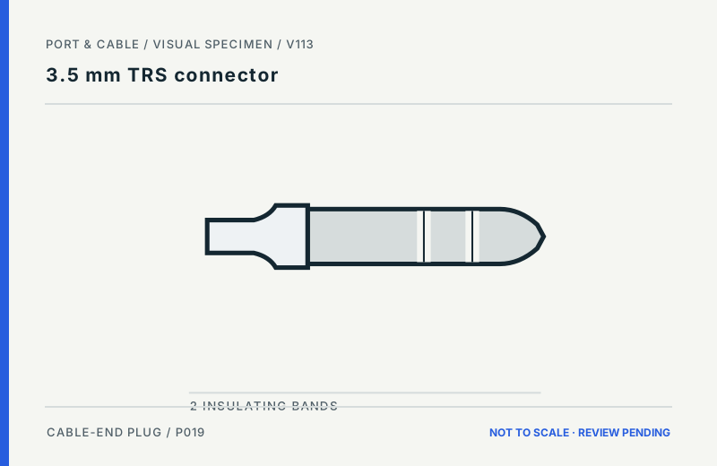
Recognize the right physical clue.
FIGURE · REVIEW PENDING
Cable-end plug. Side exterior of cable plug; longitudinal insulator cues.
What to look for
Two insulating bands / three metal sections
What the drawing does not prove
Band counts are intentional; length, spacing and tip proportions are unmeasured.
Bands cannot tell you CTIA/OMTP, microphone support or analog/digital function.
No fabrication dimensions, conductor routing, guaranteed fit or device approval. For electrical, power and optical interfaces, follow the original equipment instructions.
Figure evidence, orientation & usage rights
Uses previously recorded V112 manufacturer claim/source inspections; October 2026 supplementary public-source spot checks are documented separately, not treated as a refreshed approval.
Original Port & Cable interpretive vector, no third-party photo, copied CAD, logo or vendor drawing. Third-party product photos, logos and source drawings are not redistributed. No independent technical or rights certification is claimed.
Original claim identifiers: C019A (private workspace). Legacy evidence dates and rights assessments remain as recorded.
A 3.5 mm TRS plug has three conductive sections: tip, ring and sleeve. [C019A]
Neutrik identifies NTP3RC as a three-pole 3.5 mm male audio plug with solder termination; its customer drawing shows the plug axis at a right angle to the cable exit. [C019B]
Identify the documented form
Count the conductive plug sections before asking what signal they carry.
TRS names Tip, Ring and Sleeve conductive sections; count the plug sections rather than hidden jack springs. S022
The cited Neutrik example is a male cable plug with a right-angle cable exit, not a socket or a universal wiring map. S022 · S523
Documented identity facts; exact part and variant scope remains with each value
Nominal contacts
3S022phone plug physical contact sequence; nominal engineering count, not automatically positions, population or a device wiring map. phone plug physical contact sequence
Positions / cavity span
Not recordedNot recorded in a normalized source-scoped field. Consult the exact part/revision; no value inferred from illustrations.
Populated contacts
Not recordedNot recorded in a normalized source-scoped field. Consult the exact part/revision; no value inferred from illustrations.
Connector role
plug; plug (Neutrik NTP3RC)S022 · S022 · S523Recorded source-scoped values; named examples do not describe every family variant or establish compatibility. phone plug physical contact sequence Exact NTP3RC component role and exterior; no channel mapping or device compatibility.
Rows, pitch, dimensions, keying and view limits
Additional scoped facts; not a fabrication drawing or a mating approval
Contact rows
Not recordedNot recorded in a normalized source-scoped field. Consult the exact part/revision; no value inferred from illustrations.
Contact pitch
Not recordedNot recorded in a normalized source-scoped field. Consult the exact part/revision; no value inferred from illustrations.
Dimensions / axis
3.5 mm Nominal plug family diameterS022Recorded source-scoped values; named examples do not describe every family variant or establish compatibility. nominal_identifier; phone plug physical contact sequence
Coupling / latch
chuck-type cable strain relief (NTP3RC)S871Separate exact examples; retain each value’s source, role, axis and part scope. Exact named example NTP3RC: 3.5mm three-pole male right-angle cable plug. Exact example only; no universal geometry, electrical compatibility, fabrication approval or wiring instruction. Cable clamp range is not plug mating diameter, which remains the existing3.5mm value.
Keying / polarization
Not recordedNot recorded in a normalized source-scoped field. Consult the exact part/revision; no value inferred from illustrations.
View convention
Longitudinal plug view from the exposed tip toward the cable body: Tip → Ring → Sleeve.S022Recorded source-scoped values; named examples do not describe every family variant or establish compatibility. Existing engineering orientation text; source/part/view remains controlling.
Contact gender / arrangement
Not recordedNot recorded in a normalized source-scoped field. Consult the exact part/revision; no value inferred from illustrations.
Mounting
solder contacts (NTP3RC)S871Separate exact examples; retain each value’s source, role, axis and part scope. Exact named example NTP3RC: 3.5mm three-pole male right-angle cable plug. Exact example only; no universal geometry, electrical compatibility, fabrication approval or wiring instruction. Cable clamp range is not plug mating diameter, which remains the existing3.5mm value.
Shell / form
Not recordedNot recorded in a normalized source-scoped field. Consult the exact part/revision; no value inferred from illustrations.
Manufacturer
Neutrik (NTP3RC)S022 · S523Recorded source-scoped values; named examples do not describe every family variant or establish compatibility. Exact NTP3RC component role and exterior; no channel mapping or device compatibility.
Series
3.5 mm TRS (NTP3RC)S022 · S523Recorded source-scoped values; named examples do not describe every family variant or establish compatibility. Exact NTP3RC component role and exterior; no channel mapping or device compatibility.
Exact part / implementation
NTP3RC (NTP3RC)S022 · S523Recorded source-scoped values; named examples do not describe every family variant or establish compatibility. Exact NTP3RC component role and exterior; no channel mapping or device compatibility.
Recorded markings
Not recordedNot recorded in a normalized source-scoped field. Consult the exact part/revision; no value inferred from illustrations.
Keep this limit: TRS geometry alone is not an assignment of stereo, balanced, mono or insert service. S022
Make the next check
Check the device’s headphone, line, microphone or other documented audio role and cable wiring.
Existing source inspection and AI review remain distinct from independent technical review. A matching form does not establish a safe connection.
Recorded variant and source limits
No stereo, balanced, mono or insert function is inferred from TRS geometry alone.
No manufacturing tolerances are published.
Unbalanced stereo (Extron): Plug contact convention, read along the plug from its exposed tip toward the cable. Local ordinal 1=Tip, 2=Ring, 3=Sleeve. No universal numeric solder-lug or PCB-pad numbering is claimed.
Balanced mono (Extron): Plug contact convention, read along the plug from its exposed tip toward the cable. Local ordinal 1=Tip, 2=Ring, 3=Sleeve. No universal numeric solder-lug or PCB-pad numbering is claimed.
RODE SC4 black TRS microphone input: Plug contact convention, read along the plug from its exposed tip toward the cable. Local ordinal 1=Tip, 2=Ring, 3=Sleeve. No universal numeric solder-lug or PCB-pad numbering is claimed.
Not included. Check exact device and accessory documentation.
A boundary, not an omission to guess around.
This record is an identification starting point. It does not provide measured mating tolerances, electrical approval, or a list of verified device models. Use the original device and accessory documentation to resolve the remaining requirements.
Before you connect
What to check
Identify the jack’s intended input or output role.
Check the equipment’s signal and contact assignment.
Distinguish analog TRS from a similarly sized mini optical connection.
AI-assisted inspection is not independent engineering review. Source scope and access limitations are disclosed below. Procedural checklists are editorial requirements, not hardware measurements.
Neutrik identifies NTP3RC as a three-pole 3.5 mm male audio plug with solder termination; its customer drawing shows the plug axis at a right angle to the cable exit.
Locator: Sheet 1 of 1; upper-right side elevation. Revision A, changed 30-Jul-2012. Access: public pdf text. Exact NTP3RC qualitative exterior and perpendicular cable exit; not scale geometry or contact wiring. Raw source files are not bundled; linked observation and locator retained.
NTP3RC miniature phone plug ↗ Product identification Canonical source record S022 dated 2026-10-01. The V129 visit is recorded separately; inherited source dates are unchanged.
Neutrik NTP3RC customer drawing ST-NTP3RC ↗ Sheet 1 of 1; upper-right side elevation. Revision A, changed 30-Jul-2012. Canonical source record S523 dated 2026-10-11. The V129 visit is recorded separately; inherited source dates are unchanged.
No hardware test, independent technical approval or rights clearance is asserted.
Assessment 2026-10-22 · earliest scheduled source review 2026-12-30. This is a recorded-date assessment, not a live source check. Page-level independent review is not established by this panel.
Scoped support: Exact NTP3RC qualitative exterior and perpendicular cable exit; not scale geometry or contact wiring.
Not established / limitations: Exact NTP3RC qualitative exterior and perpendicular cable exit; not scale geometry or contact wiring. Raw source files are not bundled; linked observation and locator retained.
Locator: Sheet 1 of 1; upper-right side elevation. Revision A, changed 30-Jul-2012.
Trace 2 claims to their source records
C019A · P019
A 3.5 mm TRS plug has three conductive sections: tip, ring and sleeve.
Claim scope: Consumer identification / documented standard or product class only
Neutrik identifies NTP3RC as a three-pole 3.5 mm male audio plug with solder termination; its customer drawing shows the plug axis at a right angle to the cable exit.
Claim scope: Exact NTP3RC component role and exterior; no channel mapping or device compatibility.
Recorded evidence only. An inspection date, publisher label, source link or generated packet is not independent technical review, hardware testing, fabrication approval or a compatibility verdict.

 (private workspace)