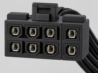
FIELD GUIDESource-led reference

P189 / PC power / Connector

ATX 24-pin main power connector

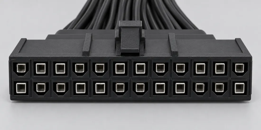
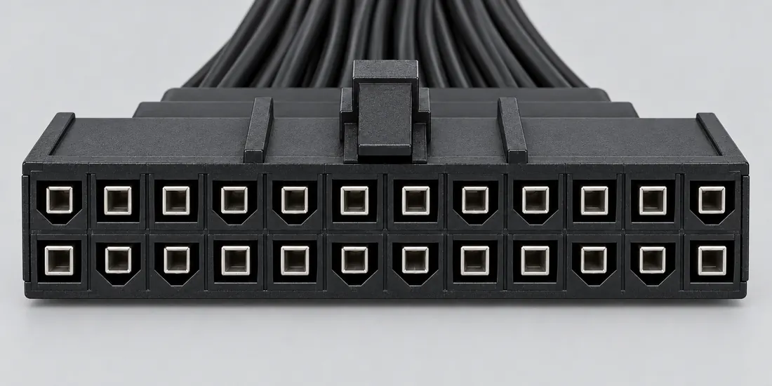
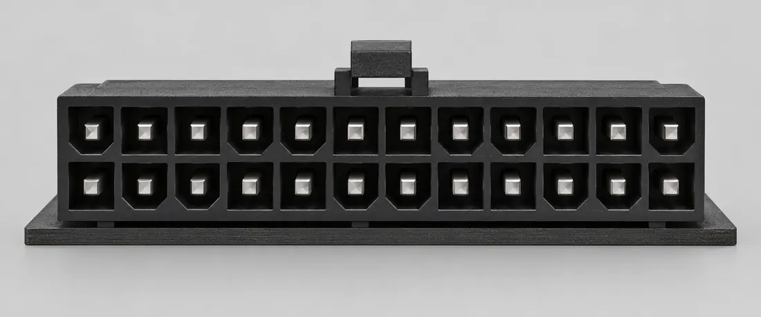
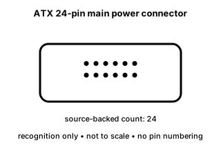
The ATX main motherboard-power interface uses a 24-position 2x12 connector form in the documented ATX design guide.

Also called ATX 24 pin 24-pin motherboard power 2x12 ATX

A 24-position shell is not enough to approve a power supply, motherboard or rewiring scheme.

Look for

Identify the motherboard and power-supply documentation together; never move terminals based on this recognition page.

Claim inspection dates: 2026-10-05, 2026-10-12 · Independent review pending

Image inspection / P189

See the view. Check its scope.

1 registered view for this reference. Different part examples are not automatically mates; all remain not to scale and independently unapproved.

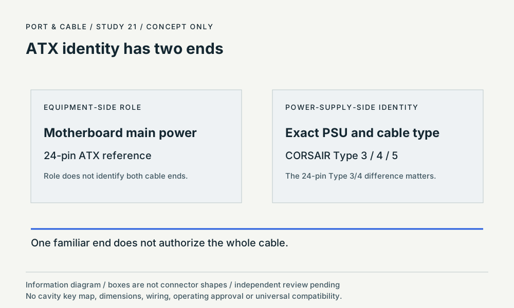
ATX identity has two ends. Role diagram only; boxes are not connector shapes. Original qualitative study; no wiring, fit or installation approval. (private workspace)

P189 / Concept — not physical geometry

ATX identity has two ends

Motherboard role and PSU cable-type checks

information hierarchy · Concept only

Not to scale. Technical and rights review pending.

Inspect view & provenance (private workspace)
INTERNAL SYSTEMS / POWER

ATX 24-pin is main system power—not a generic 24-pin harness

No. Intel’s published ATX guide identifies a 24-position motherboard main-power connector and its signals, but those motherboard-side assignments do not define the proprietary modular PSU-end wiring on every model. The same-looking cable from another supply should not be used without exact manufacturer approval.

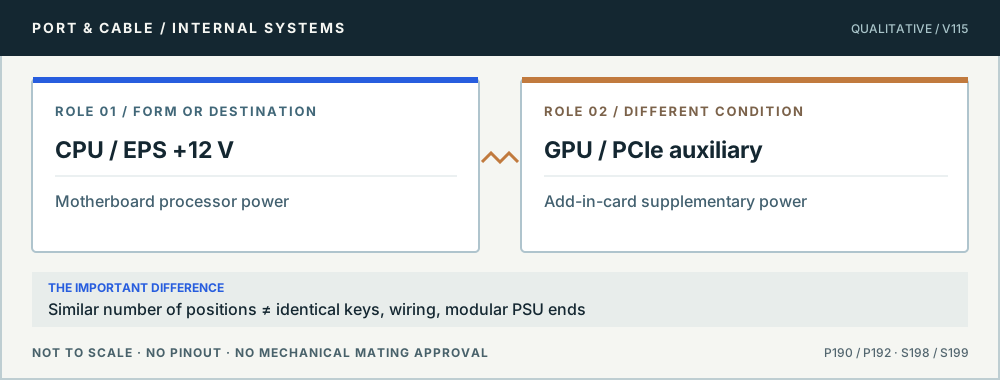
Conceptual role comparison: CPU / EPS +12 V versus GPU / PCIe auxiliary. Similar number of positions ≠ identical keys, wiring, modular PSU ends. Not to scale, no pinout or mechanical mating dimensions.
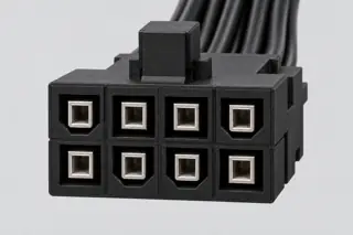
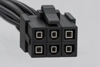
Two eight-pin power destinations. Original qualitative role diagram; not mechanical artwork, not to scale or a wiring map. Source context S198 · S199.

Three checks before proceeding

  1. Read the motherboard main-power designation and PSU manual.
  2. Use the harness expressly supplied or approved by the exact PSU manufacturer and model.
  3. If a cable has no traceable model provenance, do not energize the board through it.

One mistake to avoid

Reusing a cable from another modular PSU solely because its motherboard plug fits.

Full technical reading, sources and related identities →

Claim-specific evidence remains in the canonical record. Concept diagrams do not show any safe wiring or mechanical mating geometry.

The useful distinction

Recognize it. Then verify it.

The ATX main motherboard-power interface uses a 24-position 2x12 connector form in the documented ATX design guide. [C189A]

CORSAIR identifies the 24-pin ATX connector as the motherboard main-power connection and describes a retention latch. [C189C]

CORSAIR states that the Type 3 versus Type 4 cable difference is the 24-pin ATX cable pinout; this observation does not transfer a cable to an unlisted power supply. [C189D]

CORSAIR warns that Type 3 and Type 4 modular PSU cables are not compatible with Type 5 power supplies. [C189E]

Source-scoped identification facts

Each value retains its exact example, role and measurement axis. Facts from different parts must not be combined into an invented component.

Documented examples; not a mating drawing or compatibility approval
Nominal contacts24S197Documented position count only; V36 does not publish the signal/power assignment here.
Contact rows2 (Source-described array; C189A); 2 (39-01-2240)S197 · S935Named source examples retain separate role, part, view and axis limits; values are not a universal family specification. V36 catalogue-expansion identification fact only; not independent technical approval, fabrication data, wiring instruction or end-to-end compatibility proof. 39-01-2240. Documented role: socket housing. Molexlimited-online-catalog notice recorded. No housing-only current rating used for completed ATX harness.; KeyingNo and PolarizedYes are separate manufacturerattributes;retained in context,not a newly observed keyshape.
Contact pitch4.2 mm published contact centerline (39-01-2240)S935Named source examples retain separate role, part, view and axis limits; values are not a universal family specification. 39-01-2240. Documented role: socket housing. Molexlimited-online-catalog notice recorded. No housing-only current rating used for completed ATX harness.; KeyingNo and PolarizedYes are separate manufacturerattributes;retained in context,not a newly observed keyshape.
Connector roleplug; header; socket housing (39-01-2240)S197 · S214 · S935Named source examples retain separate role, part, view and axis limits; values are not a universal family specification. PSU main-power cable plug / motherboard header interface 39-01-2240. Documented role: socket housing. Molexlimited-online-catalog notice recorded. No housing-only current rating used for completed ATX harness.; KeyingNo and PolarizedYes are separate manufacturerattributes;retained in context,not a newly observed keyshape.
Coupling / latchlatch (Claim C189C); Positive mating lock;manufacturer separately lists polarized yes and keyed no (39-01-2240)S570 · S935Named source examples retain separate role, part, view and axis limits; values are not a universal family specification. V139 Source-scoped identification only. No complete cable assembly, universal mating, pin assignment, safe operating load, installation instruction or independent approval is established. 39-01-2240. Documented role: socket housing. Molexlimited-online-catalog notice recorded. No housing-only current rating used for completed ATX harness.; KeyingNo and PolarizedYes are separate manufacturerattributes;retained in context,not a newly observed keyshape.
ManufacturerMolex (39-01-2240)S935Named source examples retain separate role, part, view and axis limits; values are not a universal family specification. 39-01-2240. Documented role: socket housing. Molexlimited-online-catalog notice recorded. No housing-only current rating used for completed ATX harness.; KeyingNo and PolarizedYes are separate manufacturerattributes;retained in context,not a newly observed keyshape.
SeriesMini-Fit Jr. (39-01-2240)S935Named source examples retain separate role, part, view and axis limits; values are not a universal family specification. 39-01-2240. Documented role: socket housing. Molexlimited-online-catalog notice recorded. No housing-only current rating used for completed ATX harness.; KeyingNo and PolarizedYes are separate manufacturerattributes;retained in context,not a newly observed keyshape.
Exact part / implementation39-01-2240 (39-01-2240)S935Named source examples retain separate role, part, view and axis limits; values are not a universal family specification. 39-01-2240. Documented role: socket housing. Molexlimited-online-catalog notice recorded. No housing-only current rating used for completed ATX harness.; KeyingNo and PolarizedYes are separate manufacturerattributes;retained in context,not a newly observed keyshape.

Not recorded: Positions / cavity span, Populated contacts, Dimensions / axis, Contact gender / arrangement, Mounting, Keying / polarization, Shell / form, Recorded markings, View convention. Unknown fields stay unknown; illustrations supply no measurements or pin assignments.

Recorded variant and source limits
  • The normalized grid is not a physical face-view pin locator.
  • Do not apply this motherboard-side assignment to a modular PSU-side connector; those interfaces can be vendor-specific.
  • No fabrication tolerances or safe probing procedure are published.
  • Intel ATX v3 PSU main power cable connector (Molex 39-01-2240 or equivalent): Contact numbers per Table 5-1; Figure 5-2 is a pin-side view.
  • SSI 2008 dual-socket server/workstation PSU P1 baseboard connector: Contact numbers per Table 3.
  • MSI MAG B550 TOMAHAWK ATX_PWR1 board header: Board header; manual diagram labels corners 1, 12, 13, 24.
  • GIGABYTE B550 AORUS ELITE (AX) ATX board header: Board header; manual diagram labels corners 1, 12, 13, 24.
  • Intel rev 2.1a main-power cable harness: Numbered assignments only. The retrieved Intel section supplies a table but no numbered mating-face or wire-side drawing; spatial orientation is UNVERIFIED. Do not mirror these numbers onto an unidentified cable end.
  • MSI B550-A PRO ATX_PWR1: MSI p.34 board-connector drawing as printed: vertical layout, 12 upper left, 1 lower left, 24 upper right, 13 lower right. Not a cable rear view.
Report a correction to these facts →

Bounded facts, visible unknowns

Specifications and limits

ATX 24-pin main power connector facts and limitations
Documented identification24-position 2x12 ATX main-power form. [C189A]
Mechanical dimensionsNo independently reviewed mechanical drawing in V36; do not use this page for fabrication, fit testing or tolerance work.
Engineering pinoutSource-checked engineering profile available; independent review pending. Open engineering profile →
Verified device listNot included. Check exact device and accessory documentation.
A boundary, not an omission to guess around.

Use the source-backed form or position count only for identification. Resolve ratings, protocol, direction, wiring, cable construction and exact device support from the relevant equipment and component documentation.

Before you connect

What to check

  1. Identify the exact connector family and variant from the equipment or cable documentation.
  2. Keep shape, contact count, protocol, electrical rating and device support as separate facts.
  3. Do not force, rewire or adapt a connector from this recognition record; resolve the remaining requirements first.
Trace a supported connection class →

Pins & wiring

Pinout

Choose the exact wiring. Pin numbers follow its stated view; a schematic does not establish physical positions. Check your exact device before wiring.

What the status labels mean
Confirmed
Recorded research passes agree within this variant; this is not independent human review or hardware validation.
Single source
Only one underlying document, or one pass, supports this assignment.
Device-specific
Supported for the named equipment or wiring only. Check your device’s manual.
Unverified
Missing or conflicting evidence. Do not wire from this row.
Not connected
The source explicitly says NC, no contact or no pin for this wiring.
Wiring variant

Intel ATX v3 PSU main power cable connector (Molex 39-01-2240 or equivalent)

View and evidence limits

Contact numbers per Table 5-1; Figure 5-2 is a pin-side view.

  • P189 ATX 24-pin — **Agree** on usable contact assignments — Both use Intel 336521 rev 2.1a: A's PDF and B's HTML are the **same document**, not independent corroboration. A also uses SSI, MSI MAG B550 TOMAHAWK and GIGABYTE B550; B uses MSI B550-A PRO. Pin 20 is reserved/NC: A records Intel's NC/no-wire state, while B conservatively marks its usable function unverified. Neither assigns a supply to it.
  • Earlier Intel ATX12V 1.x/2.x editions and the 20-pin-only plug were not retrieved from an official host in this pass; pin 20's historical -5 V use is stated only by the SSI note, not verified for any ATX edition here.
ATX 24-pin main-power logical assignmentContact numbers per Table 5-1; Figure 5-2 is a pin-side view.SCHEMATIC · physical positions unconfirmedNot to scale · check the named wiring and device manual1: +3.3V DC (confirmed)12: +3.3V DC (confirmed)23: COM (confirmed)34: +5V DC (confirmed)45: COM (confirmed)56: +5V DC (confirmed)67: COM (confirmed)78: PWR_OK (confirmed)89: +5VSB (confirmed)910: +12V1 DC (confirmed)1011: +12V1 DC (confirmed)1112: +3.3V DC (confirmed)1213: +3.3V DC [+3.3 V default sense] (confirmed)1314: -12V DC (confirmed)1415: COM (confirmed)1516: PS_ON# (confirmed)1617: COM (confirmed)1718: COM (confirmed)1819: COM (confirmed)1920: Reserved (not_connected)2021: +5V DC (confirmed)2122: +5V DC (confirmed)2223: +5V DC (confirmed)2324: COM (confirmed)24powergrounddataConfigshieldNCUnknown
Schematic only · physical contact positions unconfirmed. Original drawing · not to scale. Scroll sideways if needed.
Intel ATX v3 PSU main power cable connector (Molex 39-01-2240 or equivalent) — source-scoped contact map
PinSignalWhat it doesStatus
1+3.3V DCPower connection (+3.3V DC). Check the specified supply.Confirmed
Sources
2+3.3V DCPower connection (+3.3V DC). Check the specified supply.Confirmed
Sources
3COMGround reference and return.Confirmed
Sources
4+5V DCPower connection (+5V DC). Check the specified supply.Confirmed
Sources
5COMGround reference and return.Confirmed
Sources
6+5V DCPower connection (+5V DC). Check the specified supply.Confirmed
Sources
7COMGround reference and return.Confirmed
Sources
8PWR_OKIndicates that the supply outputs are ready.Confirmed
Sources
9+5VSBPower connection (+5VSB). Check the specified supply.Confirmed
Sources
10+12V1 DCPower connection (+12V1 DC). Check the specified supply.Confirmed
Sources
11+12V1 DCPower connection (+12V1 DC). Check the specified supply.Confirmed
Sources
12+3.3V DCPower connection (+3.3V DC). Check the specified supply.Confirmed
Sources
13+3.3V DC [+3.3 V default sense]Power connection (+3.3V DC [+3.3 V default sense]). Check the specified supply.Confirmed
Sources
14-12V DCPower connection (-12V DC). Check the specified supply.Confirmed
Sources
15COMGround reference and return.Confirmed
Sources
16PS_ON#Requests that the power supply switch on.Confirmed
Sources
17COMGround reference and return.Confirmed
Sources
18COMGround reference and return.Confirmed
Sources
19COMGround reference and return.Confirmed
Sources
20ReservedNot connected or absent in this named wiring.Not connected
Sources
21+5V DCPower connection (+5V DC). Check the specified supply.Confirmed
Sources
22+5V DCPower connection (+5V DC). Check the specified supply.Confirmed
Sources
23+5V DCPower connection (+5V DC). Check the specified supply.Confirmed
Sources
24COMGround reference and return.Confirmed
Sources
Sources (5)

SSI 2008 dual-socket server/workstation PSU P1 baseboard connector

View and evidence limits

Contact numbers per Table 3.

  • P189 ATX 24-pin — **Agree** on usable contact assignments — Both use Intel 336521 rev 2.1a: A's PDF and B's HTML are the **same document**, not independent corroboration. A also uses SSI, MSI MAG B550 TOMAHAWK and GIGABYTE B550; B uses MSI B550-A PRO. Pin 20 is reserved/NC: A records Intel's NC/no-wire state, while B conservatively marks its usable function unverified. Neither assigns a supply to it.
  • Earlier Intel ATX12V 1.x/2.x editions and the 20-pin-only plug were not retrieved from an official host in this pass; pin 20's historical -5 V use is stated only by the SSI note, not verified for any ATX edition here.
ATX 24-pin main-power logical assignmentContact numbers per Table 3.SCHEMATIC · physical positions unconfirmedNot to scale · check the named wiring and device manual1: +3.3 VDC (confirmed)12: +3.3 VDC (confirmed)23: COM (confirmed)34: +5 VDC (confirmed)45: COM (confirmed)56: +5 VDC (confirmed)67: COM (confirmed)78: PWR OK (confirmed)89: 5 VSB (confirmed)910: +12 V4 (single_source)1011: +12 V4 (single_source)1112: +3.3 VDC (confirmed)1213: +3.3 VDC (confirmed)1314: -12 VDC (confirmed)1415: COM (confirmed)1516: PS_ON (single_source)1617: COM (confirmed)1718: COM (confirmed)1819: COM (confirmed)1920: Reserved (-5 V in ATX) (not_connected)2021: +5 VDC (confirmed)2122: +5 VDC (confirmed)2223: +5 VDC (confirmed)2324: COM (confirmed)24powergrounddataConfigshieldNCUnknown
Schematic only · physical contact positions unconfirmed. Original drawing · not to scale. Scroll sideways if needed.
SSI 2008 dual-socket server/workstation PSU P1 baseboard connector — source-scoped contact map
PinSignalWhat it doesStatus
1+3.3 VDCPower connection (+3.3 VDC). Check the specified supply.Confirmed
Sources
2+3.3 VDCPower connection (+3.3 VDC). Check the specified supply.Confirmed
Sources
3COMGround reference and return.Confirmed
Sources
4+5 VDCPower connection (+5 VDC). Check the specified supply.Confirmed
Sources
5COMGround reference and return.Confirmed
Sources
6+5 VDCPower connection (+5 VDC). Check the specified supply.Confirmed
Sources
7COMGround reference and return.Confirmed
Sources
8PWR OKIndicates that the supply outputs are ready.Confirmed
Sources
95 VSBPower connection (5 VSB). Check the specified supply.Confirmed
Sources
10+12 V4Power connection (+12 V4). Check the specified supply.Single source
Sources
11+12 V4Power connection (+12 V4). Check the specified supply.Single source
Sources
12+3.3 VDCPower connection (+3.3 VDC). Check the specified supply.Confirmed
Sources
13+3.3 VDCPower connection (+3.3 VDC). Check the specified supply.Confirmed
Sources
14-12 VDCPower connection (-12 VDC). Check the specified supply.Confirmed
Sources
15COMGround reference and return.Confirmed
Sources
16PS_ONRequests that the power supply switch on.Single source
Sources
17COMGround reference and return.Confirmed
Sources
18COMGround reference and return.Confirmed
Sources
19COMGround reference and return.Confirmed
Sources
20Reserved (-5 V in ATX)Not connected or absent in this named wiring.Not connected
Sources
21+5 VDCPower connection (+5 VDC). Check the specified supply.Confirmed
Sources
22+5 VDCPower connection (+5 VDC). Check the specified supply.Confirmed
Sources
23+5 VDCPower connection (+5 VDC). Check the specified supply.Confirmed
Sources
24COMGround reference and return.Confirmed
Sources
Sources (4)

MSI MAG B550 TOMAHAWK ATX_PWR1 board header

Device-specific wiring. Check your device’s manual before connecting or applying power.

View and evidence limits

Board header; manual diagram labels corners 1, 12, 13, 24.

  • P189 ATX 24-pin — **Agree** on usable contact assignments — Both use Intel 336521 rev 2.1a: A's PDF and B's HTML are the **same document**, not independent corroboration. A also uses SSI, MSI MAG B550 TOMAHAWK and GIGABYTE B550; B uses MSI B550-A PRO. Pin 20 is reserved/NC: A records Intel's NC/no-wire state, while B conservatively marks its usable function unverified. Neither assigns a supply to it.
  • Earlier Intel ATX12V 1.x/2.x editions and the 20-pin-only plug were not retrieved from an official host in this pass; pin 20's historical -5 V use is stated only by the SSI note, not verified for any ATX edition here.
ATX 24-pin main-power logical assignmentBoard header; manual diagram labels corners 1, 12, 13, 24.SCHEMATIC · physical positions unconfirmedNot to scale · check the named wiring and device manual1: +3.3V (device_specific)12: +3.3V (device_specific)23: Ground (device_specific)34: +5V (device_specific)45: Ground (device_specific)56: +5V (device_specific)67: Ground (device_specific)78: PWR OK (device_specific)89: 5VSB (device_specific)910: +12V (device_specific)1011: +12V (device_specific)1112: +3.3V (device_specific)1213: +3.3V (device_specific)1314: -12V (device_specific)1415: Ground (device_specific)1516: PS-ON# (device_specific)1617: Ground (device_specific)1718: Ground (device_specific)1819: Ground (device_specific)1920: Res (device_specific)2021: +5V (device_specific)2122: +5V (device_specific)2223: +5V (device_specific)2324: Ground (device_specific)24powergrounddataConfigshieldNCUnknown
Schematic only · physical contact positions unconfirmed. Original drawing · not to scale. Scroll sideways if needed.
MSI MAG B550 TOMAHAWK ATX_PWR1 board header — source-scoped contact map
PinSignalWhat it doesStatus
1+3.3VPower connection (+3.3V). Check the specified supply.Device-specific
Sources
2+3.3VPower connection (+3.3V). Check the specified supply.Device-specific
Sources
3GroundGround reference and return.Device-specific
Sources
4+5VPower connection (+5V). Check the specified supply.Device-specific
Sources
5GroundGround reference and return.Device-specific
Sources
6+5VPower connection (+5V). Check the specified supply.Device-specific
Sources
7GroundGround reference and return.Device-specific
Sources
8PWR OKIndicates that the supply outputs are ready.Device-specific
Sources
95VSBPower connection (5VSB). Check the specified supply.Device-specific
Sources
10+12VPower connection (+12V). Check the specified supply.Device-specific
Sources
11+12VPower connection (+12V). Check the specified supply.Device-specific
Sources
12+3.3VPower connection (+3.3V). Check the specified supply.Device-specific
Sources
13+3.3VPower connection (+3.3V). Check the specified supply.Device-specific
Sources
14-12VPower connection (-12V). Check the specified supply.Device-specific
Sources
15GroundGround reference and return.Device-specific
Sources
16PS-ON#Requests that the power supply switch on.Device-specific
Sources
17GroundGround reference and return.Device-specific
Sources
18GroundGround reference and return.Device-specific
Sources
19GroundGround reference and return.Device-specific
Sources
20ResControl, detection or configuration connection; check the source and device.Device-specific
Sources
21+5VPower connection (+5V). Check the specified supply.Device-specific
Sources
22+5VPower connection (+5V). Check the specified supply.Device-specific
Sources
23+5VPower connection (+5V). Check the specified supply.Device-specific
Sources
24GroundGround reference and return.Device-specific
Sources
Sources (1)

GIGABYTE B550 AORUS ELITE (AX) ATX board header

Device-specific wiring. Check your device’s manual before connecting or applying power.

View and evidence limits

Board header; manual diagram labels corners 1, 12, 13, 24.

  • P189 ATX 24-pin — **Agree** on usable contact assignments — Both use Intel 336521 rev 2.1a: A's PDF and B's HTML are the **same document**, not independent corroboration. A also uses SSI, MSI MAG B550 TOMAHAWK and GIGABYTE B550; B uses MSI B550-A PRO. Pin 20 is reserved/NC: A records Intel's NC/no-wire state, while B conservatively marks its usable function unverified. Neither assigns a supply to it.
  • Earlier Intel ATX12V 1.x/2.x editions and the 20-pin-only plug were not retrieved from an official host in this pass; pin 20's historical -5 V use is stated only by the SSI note, not verified for any ATX edition here.
ATX 24-pin main-power logical assignmentBoard header; manual diagram labels corners 1, 12, 13, 24.SCHEMATIC · physical positions unconfirmedNot to scale · check the named wiring and device manual1: 3.3V (device_specific)12: 3.3V (device_specific)23: GND (device_specific)34: +5V (device_specific)45: GND (device_specific)56: +5V (device_specific)67: GND (device_specific)78: Power Good (device_specific)89: 5VSB (stand by +5V) (device_specific)910: +12V (device_specific)1011: +12V (Only for 2x12-pin ATX) (device_specific)1112: 3.3V (Only for 2x12-pin ATX) (device_specific)1213: 3.3V (device_specific)1314: -12V (device_specific)1415: GND (device_specific)1516: PS_ON (soft On/Off) (device_specific)1617: GND (device_specific)1718: GND (device_specific)1819: GND (device_specific)1920: NC (not_connected)2021: +5V (device_specific)2122: +5V (device_specific)2223: +5V (Only for 2x12-pin ATX) (device_specific)2324: GND (Only for 2x12-pin ATX) (device_specific)24powergrounddataConfigshieldNCUnknown
Schematic only · physical contact positions unconfirmed. Original drawing · not to scale. Scroll sideways if needed.
GIGABYTE B550 AORUS ELITE (AX) ATX board header — source-scoped contact map
PinSignalWhat it doesStatus
13.3VPower connection (3.3V). Check the specified supply.Device-specific
Sources
23.3VPower connection (3.3V). Check the specified supply.Device-specific
Sources
3GNDGround reference and return.Device-specific
Sources
4+5VPower connection (+5V). Check the specified supply.Device-specific
Sources
5GNDGround reference and return.Device-specific
Sources
6+5VPower connection (+5V). Check the specified supply.Device-specific
Sources
7GNDGround reference and return.Device-specific
Sources
8Power GoodIndicates that the supply outputs are ready.Device-specific
Sources
95VSB (stand by +5V)Power connection (5VSB (stand by +5V)). Check the specified supply.Device-specific
Sources
10+12VPower connection (+12V). Check the specified supply.Device-specific
Sources
11+12V (Only for 2x12-pin ATX)Power connection (+12V (Only for 2x12-pin ATX)). Check the specified supply.Device-specific
Sources
123.3V (Only for 2x12-pin ATX)Power connection (3.3V (Only for 2x12-pin ATX)). Check the specified supply.Device-specific
Sources
133.3VPower connection (3.3V). Check the specified supply.Device-specific
Sources
14-12VPower connection (-12V). Check the specified supply.Device-specific
Sources
15GNDGround reference and return.Device-specific
Sources
16PS_ON (soft On/Off)Requests that the power supply switch on.Device-specific
Sources
17GNDGround reference and return.Device-specific
Sources
18GNDGround reference and return.Device-specific
Sources
19GNDGround reference and return.Device-specific
Sources
20NCNot connected or absent in this named wiring.Not connected
Sources
21+5VPower connection (+5V). Check the specified supply.Device-specific
Sources
22+5VPower connection (+5V). Check the specified supply.Device-specific
Sources
23+5V (Only for 2x12-pin ATX)Power connection (+5V (Only for 2x12-pin ATX)). Check the specified supply.Device-specific
Sources
24GND (Only for 2x12-pin ATX)Ground reference and return.Device-specific
Sources
Sources (1)

Intel rev 2.1a main-power cable harness

View and evidence limits

Numbered assignments only. The retrieved Intel section supplies a table but no numbered mating-face or wire-side drawing; spatial orientation is UNVERIFIED. Do not mirror these numbers onto an unidentified cable end.

  • P189 ATX 24-pin — **Agree** on usable contact assignments — Both use Intel 336521 rev 2.1a: A's PDF and B's HTML are the **same document**, not independent corroboration. A also uses SSI, MSI MAG B550 TOMAHAWK and GIGABYTE B550; B uses MSI B550-A PRO. Pin 20 is reserved/NC: A records Intel's NC/no-wire state, while B conservatively marks its usable function unverified. Neither assigns a supply to it.
  • Intel names cable housing Molex 39-01-2240 and motherboard mate 44206-0007. Pin 13 combines power and the default sense wire.
  • Pin 20 is Reserved, with NC in the Color column. This pass does not infer a usable function from that notation.
  • Pin 20 remains unverified as a usable function in both variants. Intel table-only spatial orientation and proprietary modular PSU endpoint pinouts are unverified.
ATX 24-pin main-power logical assignmentNumbered assignments only. The retrieved Intel section supplies a table but no numbered mating-face or wire-side drawing; spatial orientation is UNVERIFIED. Do not mirror these numbers onto an unidentified cable end.SCHEMATIC · physical positions unconfirmedNot to scale · check the named wiring and device manual1: +3.3V DC (confirmed)12: +3.3V DC (confirmed)23: COM (confirmed)34: +5V DC (confirmed)45: COM (confirmed)56: +5V DC (confirmed)67: COM (confirmed)78: PWR_OK (confirmed)89: +5VSB (confirmed)910: +12V1 DC (confirmed)1011: +12V1 DC (confirmed)1112: +3.3V DC (confirmed)1213: +3.3V DC [+3.3 V default sense] (confirmed)1314: -12V DC (confirmed)1415: COM (confirmed)1516: PS_ON# (confirmed)1617: COM (confirmed)1718: COM (confirmed)1819: COM (confirmed)1920: Not confirmed (unverified)2021: +5V DC (confirmed)2122: +5V DC (confirmed)2223: +5V DC (confirmed)2324: COM (confirmed)24powergrounddataConfigshieldNCUnknown
Schematic only · physical contact positions unconfirmed. Original drawing · not to scale. Scroll sideways if needed.
Intel rev 2.1a main-power cable harness — source-scoped contact map
PinSignalWhat it doesStatus
1+3.3V DCPower connection (+3.3V DC). Check the specified supply.Confirmed
Sources
2+3.3V DCPower connection (+3.3V DC). Check the specified supply.Confirmed
Sources
3COMGround reference and return.Confirmed
Sources
4+5V DCPower connection (+5V DC). Check the specified supply.Confirmed
Sources
5COMGround reference and return.Confirmed
Sources
6+5V DCPower connection (+5V DC). Check the specified supply.Confirmed
Sources
7COMGround reference and return.Confirmed
Sources
8PWR_OKIndicates that the supply outputs are ready.Confirmed
Sources
9+5VSBPower connection (+5VSB). Check the specified supply.Confirmed
Sources
10+12V1 DCPower connection (+12V1 DC). Check the specified supply.Confirmed
Sources
11+12V1 DCPower connection (+12V1 DC). Check the specified supply.Confirmed
Sources
12+3.3V DCPower connection (+3.3V DC). Check the specified supply.Confirmed
Sources
13+3.3V DC [+3.3 V default sense]Power connection (+3.3V DC [+3.3 V default sense]). Check the specified supply.Confirmed
Sources
14-12V DCPower connection (-12V DC). Check the specified supply.Confirmed
Sources
15COMGround reference and return.Confirmed
Sources
16PS_ON#Requests that the power supply switch on.Confirmed
Sources
17COMGround reference and return.Confirmed
Sources
18COMGround reference and return.Confirmed
Sources
19COMGround reference and return.Confirmed
Sources
20Not confirmedNo settled assignment. Do not wire from this row.Unverified
Sources
21+5V DCPower connection (+5V DC). Check the specified supply.Confirmed
Sources
22+5V DCPower connection (+5V DC). Check the specified supply.Confirmed
Sources
23+5V DCPower connection (+5V DC). Check the specified supply.Confirmed
Sources
24COMGround reference and return.Confirmed
Sources
Sources (7)

MSI B550-A PRO ATX_PWR1

Device-specific wiring. Check your device’s manual before connecting or applying power.

View and evidence limits

MSI p.34 board-connector drawing as printed: vertical layout, 12 upper left, 1 lower left, 24 upper right, 13 lower right. Not a cable rear view.

  • P189 ATX 24-pin — **Agree** on usable contact assignments — Both use Intel 336521 rev 2.1a: A's PDF and B's HTML are the **same document**, not independent corroboration. A also uses SSI, MSI MAG B550 TOMAHAWK and GIGABYTE B550; B uses MSI B550-A PRO. Pin 20 is reserved/NC: A records Intel's NC/no-wire state, while B conservatively marks its usable function unverified. Neither assigns a supply to it.
  • MSI does not identify a pin-13 sense function; its table is retained separately.
  • Pin 20 remains unverified as a usable function in both variants. Intel table-only spatial orientation and proprietary modular PSU endpoint pinouts are unverified.
ATX 24-pin main-power logical assignmentMSI p.34 board-connector drawing as printed: vertical layout, 12 upper left, 1 lower left, 24 upper right, 13 lower right. Not a cable rear view.SCHEMATIC · physical positions unconfirmedNot to scale · check the named wiring and device manual1: +3.3V (device_specific)12: +3.3V (device_specific)23: Ground (device_specific)34: +5V (device_specific)45: Ground (device_specific)56: +5V (device_specific)67: Ground (device_specific)78: PWR OK (device_specific)89: 5VSB (device_specific)910: +12V (device_specific)1011: +12V (device_specific)1112: +3.3V (device_specific)1213: +3.3V (device_specific)1314: -12V (device_specific)1415: Ground (device_specific)1516: PS-ON# (device_specific)1617: Ground (device_specific)1718: Ground (device_specific)1819: Ground (device_specific)1920: Not confirmed (unverified)2021: +5V (device_specific)2122: +5V (device_specific)2223: +5V (device_specific)2324: Ground (device_specific)24powergrounddataConfigshieldNCUnknown
Schematic only · physical contact positions unconfirmed. Original drawing · not to scale. Scroll sideways if needed.
MSI B550-A PRO ATX_PWR1 — source-scoped contact map
PinSignalWhat it doesStatus
1+3.3VPower connection (+3.3V). Check the specified supply.Device-specific
Sources
2+3.3VPower connection (+3.3V). Check the specified supply.Device-specific
Sources
3GroundGround reference and return.Device-specific
Sources
4+5VPower connection (+5V). Check the specified supply.Device-specific
Sources
5GroundGround reference and return.Device-specific
Sources
6+5VPower connection (+5V). Check the specified supply.Device-specific
Sources
7GroundGround reference and return.Device-specific
Sources
8PWR OKIndicates that the supply outputs are ready.Device-specific
Sources
95VSBPower connection (5VSB). Check the specified supply.Device-specific
Sources
10+12VPower connection (+12V). Check the specified supply.Device-specific
Sources
11+12VPower connection (+12V). Check the specified supply.Device-specific
Sources
12+3.3VPower connection (+3.3V). Check the specified supply.Device-specific
Sources
13+3.3VPower connection (+3.3V). Check the specified supply.Device-specific
Sources
14-12VPower connection (-12V). Check the specified supply.Device-specific
Sources
15GroundGround reference and return.Device-specific
Sources
16PS-ON#Requests that the power supply switch on.Device-specific
Sources
17GroundGround reference and return.Device-specific
Sources
18GroundGround reference and return.Device-specific
Sources
19GroundGround reference and return.Device-specific
Sources
20Not confirmedNo settled assignment. Do not wire from this row.Unverified
Sources
21+5VPower connection (+5V). Check the specified supply.Device-specific
Sources
22+5VPower connection (+5V). Check the specified supply.Device-specific
Sources
23+5VPower connection (+5V). Check the specified supply.Device-specific
Sources
24GroundGround reference and return.Device-specific
Sources
Sources (3)

What is not established

This field note does not approve a connection, adapter, cable assembly, rewiring scheme or fabricated part. It intentionally omits unsupported pin assignments and mechanical tolerances.

Your next step

Move from the form to the requirement.

The source trail

Evidence for this page

AI-assisted inspection is not independent engineering review. Source scope and access limitations are disclosed below. Procedural checklists are editorial requirements, not hardware measurements.

Back to first citation ↑
C189ASource checked · pending review

Intel documents the ATX main power connector as a 24-pin / 2x12 connector interface in the cited design guide.

Intel · ATX Version 3.0 — Main Power Connector (Required) ↗

Locator: Main power connector section
Access: public page. Identification/reference scope only. V36 does not convert this source into a universal pinout, fabrication drawing, electrical approval or end-to-end compatibility verdict.

S197: full source recordInspect review dependencies → (private workspace)

Claim scope: V36 catalogue-expansion identification fact only; not independent technical approval, fabrication data, wiring instruction or end-to-end compatibility proof.. Next review due 2027-01-03.

Back to first citation ↑
C189CSource checked · pending review

CORSAIR identifies the 24-pin ATX connector as the motherboard main-power connection and describes a retention latch.

CORSAIR · ATX motherboard role and separable PCIe cable portions ↗

Locator: 24-pin ATX connector and 6-pin / 6+2-pin PCIe sections. Text inspected; article images unavailable.
Access: public page. Source-scoped identification only. No complete cable assembly, universal mating, pin assignment, safe operating load, installation instruction or independent approval is established.

S570: full source recordInspect review dependencies → (private workspace)

Claim scope: V139 Source-scoped identification only. No complete cable assembly, universal mating, pin assignment, safe operating load, installation instruction or independent approval is established.. Next review due 2027-01-10.

Back to first citation ↑
C189DSource checked · pending review

CORSAIR states that the Type 3 versus Type 4 cable difference is the 24-pin ATX cable pinout; this observation does not transfer a cable to an unlisted power supply.

CORSAIR · 24-pin cable types: the exception matters ↗

Locator: Disclaimer items 2 and 3, above the model table. Model compatibility icons not interpreted.
Access: public page. Source-scoped identification only. No complete cable assembly, universal mating, pin assignment, safe operating load, installation instruction or independent approval is established.

S571: full source recordInspect review dependencies → (private workspace)

Claim scope: V139 Source-scoped identification only. No complete cable assembly, universal mating, pin assignment, safe operating load, installation instruction or independent approval is established.. Next review due 2027-01-10.

Back to first citation ↑
C189ESource checked · pending review

CORSAIR warns that Type 3 and Type 4 modular PSU cables are not compatible with Type 5 power supplies.

CORSAIR · 24-pin cable types: the exception matters ↗

Locator: Disclaimer items 2 and 3, above the model table. Model compatibility icons not interpreted.
Access: public page. Source-scoped identification only. No complete cable assembly, universal mating, pin assignment, safe operating load, installation instruction or independent approval is established.

S571: full source recordInspect review dependencies → (private workspace)

Claim scope: V139 Source-scoped identification only. No complete cable assembly, universal mating, pin assignment, safe operating load, installation instruction or independent approval is established.. Next review due 2027-01-10.

Suggest a correction to this field note →

Put this field note to work.

Add to discovery trayRecord an unsaved candidate (private workspace)

Candidate selection does not confirm the identity or capabilities of your physical item.

MAIN & AUXILIARY POWER / SOURCE-QUALIFIED IDENTITY

Keep the component and application separate.

Motherboard main power

CORSAIR / 24-pin ATX section

Role
Motherboard connection, not a generic PSU-side socket.
Distinction
The retention latch belongs to a documented connector role.
Established
Identify the equipment function before comparing the plastic outline.
Not established
Exact motherboard and PSU model; cable order and pinout.
Next check
Read the motherboard and power-supply documentation together.

Source-field reference; no physical view assigned to this row.

Evidence, component scope & limits

Observed . C189C

ATX motherboard role and separable PCIe cable portions ↗
24-pin ATX connector and 6-pin / 6+2-pin PCIe sections. Text inspected; article images unavailable.
S570 · observation date 2026-10-12. The guide identifies motherboard main power and describes using the six-position portion of a documented 6+2 cable. It does not identify every bare housing or authorize an unknown PSU cable.

The observation date is not a drawing revision. No wiring, fit or installation approval.

The 24-pin cable-type exception

CORSAIR / Type 3, Type 4 and Type 5 warning

Role
Manufacturer-specific modular cable families.
Distinction
Type 3 and Type 4 differ at the 24-pin ATX pinout; neither is Type 5 compatible.
Established
A familiar motherboard-end shape does not establish the PSU-side cable match.
Not established
Compatibility for an unlisted model or another manufacturer.
Next check
Resolve the exact PSU model and cable type; do not reuse a cable on shape alone.

Source-field reference; no physical view assigned to this row.

Evidence, component scope & limits

Observed . C189D · C189E

24-pin cable types: the exception matters ↗
Disclaimer items 2 and 3, above the model table. Model compatibility icons not interpreted.
S571 · observation date 2026-10-12. The manufacturer distinguishes Type 3 and Type 4 specifically at the 24-pin cable pinout and excludes both from Type 5 supplies. This is a manufacturer-specific warning, not a universal type system.

The observation date is not a drawing revision. No wiring, fit or installation approval.

Read the complete power identity guide →

Evidence behind this page

Scope first. Source second. Approval separate.

3 linked sources · 4 scoped claims · 0 sources with inspection/access flags.

Page scope: catalogue_expansion_v36

Assessment 2026-10-22 · earliest scheduled source review 2027-01-03. This is a recorded-date assessment, not a live source check. Page-level independent review is not established by this panel.

Inspect 3 source scopes, access limits and dates

S197 · ATX Version 3.0 — Main Power Connector (Required)

Intel · Manufacturer / product-owner domain · inspected 2026-10-05 · due 2027-01-03

Within inspection window

Scoped support: Identifies the ATX main power connector as a 24-pin / 2x12 Mini-Fit Jr.-family interface in the documented ATX design guide.

Not established / limitations: Identification/reference scope only. V36 does not convert this source into a universal pinout, fabrication drawing, electrical approval or end-to-end compatibility verdict.

Locator: Main power connector section

S570 · ATX motherboard role and separable PCIe cable portions

CORSAIR · Unclassified publisher domain · inspected 2026-10-12 · due 2027-01-10

Within inspection window

Scoped support: The guide identifies motherboard main power and describes using the six-position portion of a documented 6+2 cable. It does not identify every bare housing or authorize an unknown PSU cable.

Not established / limitations: Source-scoped identification only. No complete cable assembly, universal mating, pin assignment, safe operating load, installation instruction or independent approval is established.

Locator: 24-pin ATX connector and 6-pin / 6+2-pin PCIe sections. Text inspected; article images unavailable.

S571 · 24-pin cable types: the exception matters

CORSAIR · Unclassified publisher domain · inspected 2026-10-12 · due 2027-01-10

Within inspection window

Scoped support: The manufacturer distinguishes Type 3 and Type 4 specifically at the 24-pin cable pinout and excludes both from Type 5 supplies. This is a manufacturer-specific warning, not a universal type system.

Not established / limitations: Source-scoped identification only. No complete cable assembly, universal mating, pin assignment, safe operating load, installation instruction or independent approval is established.

Locator: Disclaimer items 2 and 3, above the model table. Model compatibility icons not interpreted.

Trace 4 claims to their source records

C189A · P189

Intel documents the ATX main power connector as a 24-pin / 2x12 connector interface in the cited design guide.

Claim scope: V36 catalogue-expansion identification fact only; not independent technical approval, fabrication data, wiring instruction or end-to-end compatibility proof.

Source links: S197 · Evidence trail → (private workspace)

C189C · P189

CORSAIR identifies the 24-pin ATX connector as the motherboard main-power connection and describes a retention latch.

Claim scope: V139 Source-scoped identification only. No complete cable assembly, universal mating, pin assignment, safe operating load, installation instruction or independent approval is established.

Source links: S570 · Evidence trail → (private workspace)

C189D · P189

CORSAIR states that the Type 3 versus Type 4 cable difference is the 24-pin ATX cable pinout; this observation does not transfer a cable to an unlisted power supply.

Claim scope: V139 Source-scoped identification only. No complete cable assembly, universal mating, pin assignment, safe operating load, installation instruction or independent approval is established.

Source links: S571 · Evidence trail → (private workspace)

C189E · P189

CORSAIR warns that Type 3 and Type 4 modular PSU cables are not compatible with Type 5 power supplies.

Claim scope: V139 Source-scoped identification only. No complete cable assembly, universal mating, pin assignment, safe operating load, installation instruction or independent approval is established.

Source links: S571 · Evidence trail → (private workspace)

Prepare this page for review → (private workspace)Read the evidence method →

Recorded evidence only. An inspection date, publisher label, source link or generated packet is not independent technical review, hardware testing, fabrication approval or a compatibility verdict.