FIELD GUIDESource-led reference

P114 / Legacy computer / Connector

DE-9 D-sub (commonly called DB9)

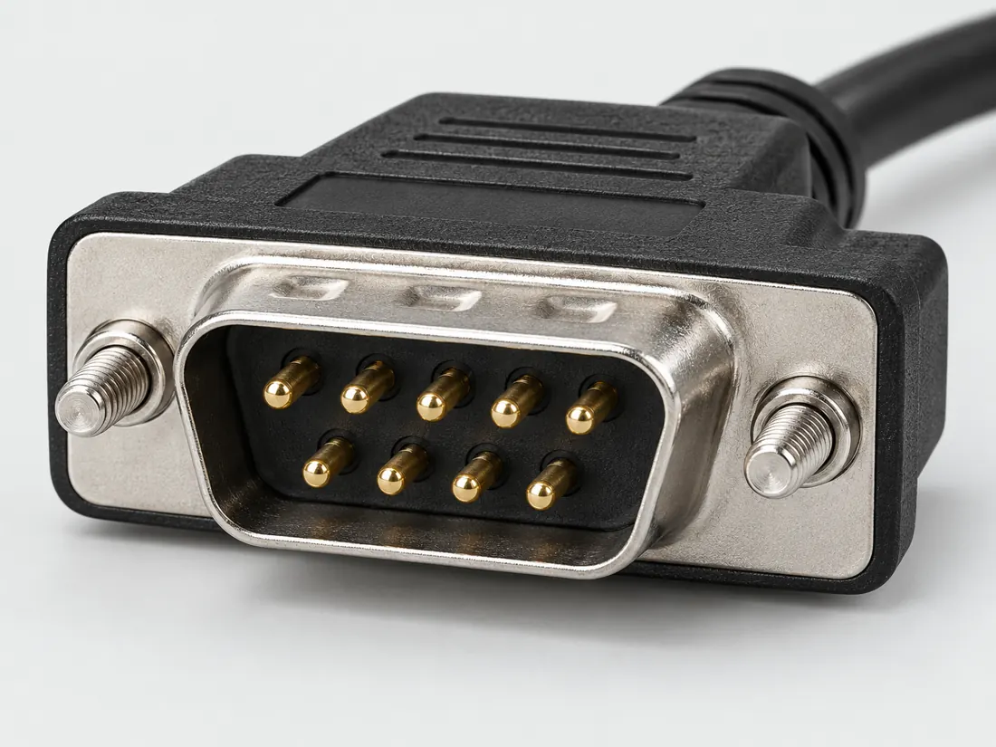
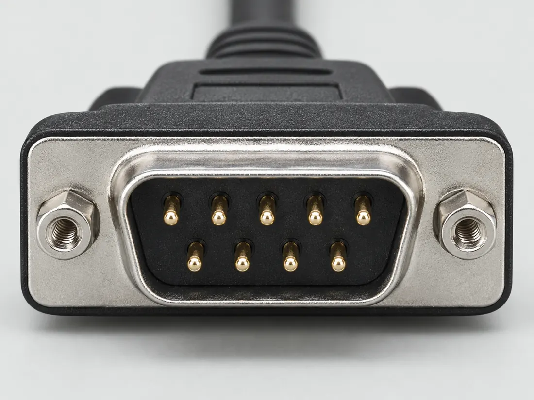
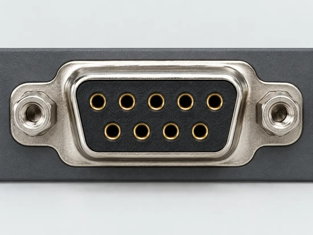
A two-row, nine-position D-sub form often associated with serial ports; the port documentation still controls its function.

Also called DB9 DE9 9 pin serial RS232 plug

Nine positions are not a serial pinout.

Look for

Compare the two rows, with five and four nominal positions. Do not treat the signal name as proven by the shell.

Claim inspection dates: 2026-10-03, 2026-10-13 · Independent review pending

Image inspection / P114

See the view. Check its scope.

1 registered view for this reference. Different part examples are not automatically mates; all remain not to scale and independently unapproved.

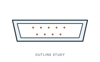
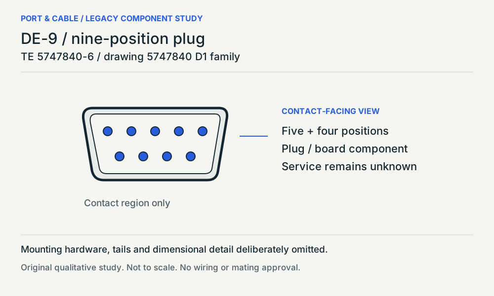
DE-9 / nine-position plug. Contact-facing view / source longer row above. Two rows: five positions above four; Named board component, not a serial port; Optional hardware and contact numbering omitted. Original qualitative study, not a pinout. (private workspace)

P114 / Source-observed physical study

DE-9 / nine-position plug

TE 5747840-6 / drawing 5747840 D1 family

Contact-facing view / source longer row above · Other declared component

Not to scale. Technical and rights review pending.

Inspect view & provenance (private workspace)
V117 / READER FIELD GUIDE / AV & LEGACY

Before you connect or replace

A nine-position D-sub is not necessarily RS-232

No. DE-9 describes a common nine-position shell; RS-232 is only one possible application. Read the actual equipment pin assignment and signalling convention.

Three checks and exact source trail ↗

Editorial decision guidance only. A connector identity or nominal pitch does not establish approved mating, safe wiring or a supported device combination.

Inspect the illustrationUnnumbered face-pattern sketch · larger view & look-alikes
DE-9 D-sub (commonly called DB9) — unnumbered face-pattern sketch; role not specified; original, not-to-scale identification schematic; drawing review pending
View Unnumbered face-pattern sketchDepiction Role not specifiedNot to scale · independent drawing review pending

Read the view

D-shaped outline with two rows of illustrative positions

Five marks are drawn above four; this is not a numbered front/rear pair. Plug versus socket remains unspecified.

About the marks: Read the documented position count separately from electrical assignments.

What it cannot establish: The shell does not identify a serial pinout or prove the port function.

Enlargement changes display size only. It does not reveal measured geometry, a pin assignment or an approved mating combination.

Compare a likely look-alike

Read the underlying references: S092. Artwork interpretation remains review-pending.

How to read connector illustrations →

The useful distinction

Recognize it. Then verify it.

A two-row, nine-position D-sub form often associated with serial ports; the port documentation still controls its function. [C114A]

It describes RS-232 as a common application, not an identity guaranteed for every such socket. [C114B]

TE identifies 5747840-6 as a nine-position, two-row plug mounted at right angles to a printed circuit board. [C114C]

Drawing 5747840 D1 shows five contacts above four in the contact-facing view, separately from the recommended board layout. [C114D]

Source-scoped identification facts

Each value retains its exact example, role and measurement axis. Facts from different parts must not be combined into an invented component.

Documented examples; not a mating drawing or compatibility approval
Nominal contacts9S092Nine nominal positions; the guide cautions that some D-sub connectors do not populate every contact.
Positions / cavity span9 (Claim C114A); 9 (Claim C114C)S092 · S625Recorded source-scoped values; named examples do not describe every family variant or establish compatibility. Identification and explicitly scoped documentation only; not an end-to-end connection approval Exact component role and mounting only; this is not an identification of the service on a complete device.
Contact rows2 (Claim C114C); 2 (5747840-6)S625 · S625Named source examples retain separate role, part, view and axis limits; values are not a universal family specification. TE identifies 5747840-6 as a nine-position, two-row plug mounted at right angles to a printed circuit board. | Exact component role and mounting only; this is not an identification of the service on a complete device. 5747840-6. Documented role: plug. Exact named part only. Product specification is not a specimen measurement or interoperability approval.
Contact pitch2.74 mm centerline (5747840-6)S625Named source examples retain separate role, part, view and axis limits; values are not a universal family specification. 5747840-6. Documented role: plug. Exact named part only. Product specification is not a specimen measurement or interoperability approval.
Dimensions / axis2.84 mm row-to-row spacing (5747840-6)S625Named source examples retain separate role, part, view and axis limits; values are not a universal family specification. 5747840-6. Documented role: plug. Exact named part only. Product specification is not a specimen measurement or interoperability approval.
Connector roleplug (5747840-6)S625Named source examples retain separate role, part, view and axis limits; values are not a universal family specification. 5747840-6. Documented role: plug. Exact named part only. Product specification is not a specimen measurement or interoperability approval.
MountingFixed female screwlocks; boardlock PCB retention; right-angle boardmount (5747840-6)S625Not recorded in a normalized source-scoped field. Consult the exact part/revision; no value inferred from illustrations. 5747840-6. Documented role: plug. Exact named part only. Product specification is not a specimen measurement or interoperability approval.
ManufacturerTE Connectivity (5747840-6)S625Named source examples retain separate role, part, view and axis limits; values are not a universal family specification. 5747840-6. Documented role: plug. Exact named part only. Product specification is not a specimen measurement or interoperability approval.
SeriesAMPLIMITE HD-20 (5747840-6)S625Named source examples retain separate role, part, view and axis limits; values are not a universal family specification. 5747840-6. Documented role: plug. Exact named part only. Product specification is not a specimen measurement or interoperability approval.
Exact part / implementation5747840-6 (5747840-6)S625Named source examples retain separate role, part, view and axis limits; values are not a universal family specification. 5747840-6. Documented role: plug. Exact named part only. Product specification is not a specimen measurement or interoperability approval.

Not recorded: Populated contacts, Contact gender / arrangement, Coupling / latch, Keying / polarization, Shell / form, Recorded markings, View convention. Unknown fields stay unknown; illustrations supply no measurements or pin assignments.

Recorded variant and source limits
  • Check the exact device manual before wiring or applying power.
  • IBM Personal Computer AT Serial/Parallel Adapter serial port (DTE), 9-pin D-shell: Contact numbers as in IBM figure (the figure shows the adapter connector with 1-5 and 6-9 rows); arrows give signal direction relative to the adapter.
  • PC DTE 9-pin serial interface (TI SLLA037A): D-sub contact numbers 1-9 as moulded. TI: DTE is a male-pin connector (female housing per TI's wording); no face-view orientation is transferred.
  • SGI O2 serial ports 1 and 2 (DB9): D-sub contact numbers 1-9 as moulded. TI: DTE is a male-pin connector (female housing per TI's wording); no face-view orientation is transferred.
  • Doug Fleenor Design 2322DMX front-panel DB-9M RS-232 port (device-specific): D-sub contact numbers 1-9 as moulded. TI: DTE is a male-pin connector (female housing per TI's wording); no face-view orientation is transferred.
  • Screwlocks/boardlocks/boardmount are retention and mounting evidence, not mating polarization. Recorded source context: Fixed female screwlocks; boardlock PCB retention; right-angle boardmount / 5747840-6
Report a correction to these facts →

Bounded facts, visible unknowns

Specifications and limits

DE-9 D-sub (commonly called DB9) facts and limitations
Documented identificationThe guide lists the common DB9 form as nine positions in rows of five and four. [C114A]
Important distinctionIt describes RS-232 as a common application, not an identity guaranteed for every such socket. [C114B]
Source-scoped component observationTE identifies 5747840-6 as a nine-position, two-row plug mounted at right angles to a printed circuit board. [C114C]
Source-scoped component observationDrawing 5747840 D1 shows five contacts above four in the contact-facing view, separately from the recommended board layout. [C114D]
Mechanical dimensionsNo independently approved mechanical dimensions. Do not use this record for fabrication or fit testing.
Engineering pinoutSource-checked engineering profile available; independent review pending. Open engineering profile →
Verified device listNot included. Check exact device and accessory documentation.
A boundary, not an omission to guess around.

Record the exact device model and the label beside the port. Obtain its manual and the accessory documentation. Keep unknown properties unknown instead of filling them from a visually similar item.

Before you connect

What to check

  1. Record the exact device and serial interface type.
  2. Check the required cable wiring and direction in the manual.
  3. Confirm OS and driver support for any converter.
Trace a supported connection class →

Pins & wiring

Pinout

Choose the exact wiring. Pin numbers follow its stated view; a schematic does not establish physical positions. Check your exact device before wiring.

What the status labels mean
Confirmed
Recorded research passes agree within this variant; this is not independent human review or hardware validation.
Single source
Only one underlying document, or one pass, supports this assignment.
Device-specific
Supported for the named equipment or wiring only. Check your device’s manual.
Unverified
Missing or conflicting evidence. Do not wire from this row.
Not connected
The source explicitly says NC, no contact or no pin for this wiring.
Wiring variant

IBM Personal Computer AT Serial/Parallel Adapter serial port (DTE), 9-pin D-shell

Device-specific wiring. Check your device’s manual before connecting or applying power.

View and evidence limits

Contact numbers as in IBM figure (the figure shows the adapter connector with 1-5 and 6-9 rows); arrows give signal direction relative to the adapter.

  • P114 DE-9 (RS-232 DTE) — **Agree** on all 9 (1 DCD, 2 RxD, 3 TxD, 4 DTR, 5 ground, 6 DSR, 7 RTS, 8 CTS, 9 RI) — A: IBM PC AT. B: TI SLLA037A and SGI O2.
  • TIA-232-F and TIA-574 (the 9-position DTE assignment) are paywalled and were not accessed; rows rely on IBM.
  • Not established.
  • CAN (CiA 303-1), Atari/Commodore joystick, CGA/EGA/MDA video, Profibus and other DE-9 uses were not established from primary documents in this pass.
DE-9 D-sub (RS-232 DTE and other uses) engineering referenceContact numbers as in IBM figure (the figure shows the adapter connector with 1-5 and 6-9 rows); arrows give signal direction relative to the adapter.SCHEMATIC · physical positions unconfirmedNot to scale · check the named wiring and device manual1: Carrier Detect (device_specific)12: Receive Data (device_specific)23: Transmit Data (device_specific)34: Data Terminal Ready (device_specific)45: Signal Ground (device_specific)56: Data Set Ready (device_specific)67: Request To Send (device_specific)78: Clear To Send (device_specific)89: Ring Indicator (device_specific)9powergrounddataConfigshieldNCUnknown
Schematic only · physical contact positions unconfirmed. Original drawing · not to scale. Scroll sideways if needed.
IBM Personal Computer AT Serial/Parallel Adapter serial port (DTE), 9-pin D-shell — source-scoped contact map
PinSignalWhat it doesStatus
1Carrier DetectIndicates a detected serial carrier.Device-specific
Sources
2Receive DataSignal conductor. Pair, polarity and direction follow this named wiring.Device-specific
Sources
3Transmit DataSignal conductor. Pair, polarity and direction follow this named wiring.Device-specific
Sources
4Data Terminal ReadySignal conductor. Pair, polarity and direction follow this named wiring.Device-specific
Sources
5Signal GroundControl, detection or configuration connection; check the source and device.Device-specific
Sources
6Data Set ReadySignal conductor. Pair, polarity and direction follow this named wiring.Device-specific
Sources
7Request To SendControl, detection or configuration connection; check the source and device.Device-specific
Sources
8Clear To SendControl, detection or configuration connection; check the source and device.Device-specific
Sources
9Ring IndicatorControl, detection or configuration connection; check the source and device.Device-specific
Sources
Sources (1)

PC DTE 9-pin serial interface (TI SLLA037A)

View and evidence limits

D-sub contact numbers 1-9 as moulded. TI: DTE is a male-pin connector (female housing per TI's wording); no face-view orientation is transferred.

  • P114 DE-9 (RS-232 DTE) — **Agree** on all 9 (1 DCD, 2 RxD, 3 TxD, 4 DTR, 5 ground, 6 DSR, 7 RTS, 8 CTS, 9 RI) — A: IBM PC AT. B: TI SLLA037A and SGI O2.
  • TIA-232-F and EIA/TIA-574 are paywalled and were not read; the DTE variant rests on TI and SGI manufacturer documents.
  • Not listed in the manual; neither connection nor non-connection is established.
  • DCE-side (modem) pinouts, CAN (CiA 303-1), game/joystick, video (CGA/EGA) and proprietary uses were not established in this pass.
DE-9 D-sub (RS-232 DTE and other uses) engineering referenceD-sub contact numbers 1-9 as moulded. TI: DTE is a male-pin connector (female housing per TI's wording); no face-view orientation is transferred.SCHEMATIC · physical positions unconfirmedNot to scale · check the named wiring and device manual1: DCD (single_source)12: RD (single_source)23: TD (single_source)34: DTR (single_source)45: Signal Ground (confirmed)56: DSR (single_source)67: RTS (single_source)78: CTS (single_source)89: RI (single_source)9powergrounddataConfigshieldNCUnknown
Schematic only · physical contact positions unconfirmed. Original drawing · not to scale. Scroll sideways if needed.
PC DTE 9-pin serial interface (TI SLLA037A) — source-scoped contact map
PinSignalWhat it doesStatus
1DCDIndicates a detected serial carrier.Single source
Sources
2RDControl, detection or configuration connection; check the source and device.Single source
Sources
3TDControl, detection or configuration connection; check the source and device.Single source
Sources
4DTRControl, detection or configuration connection; check the source and device.Single source
Sources
5Signal GroundControl, detection or configuration connection; check the source and device.Confirmed
Sources
6DSRControl, detection or configuration connection; check the source and device.Single source
Sources
7RTSRequests permission to send serial data.Single source
Sources
8CTSIndicates permission to send serial data.Single source
Sources
9RIControl, detection or configuration connection; check the source and device.Single source
Sources
Sources (2)

SGI O2 serial ports 1 and 2 (DB9)

View and evidence limits

D-sub contact numbers 1-9 as moulded. TI: DTE is a male-pin connector (female housing per TI's wording); no face-view orientation is transferred.

  • P114 DE-9 (RS-232 DTE) — **Agree** on all 9 (1 DCD, 2 RxD, 3 TxD, 4 DTR, 5 ground, 6 DSR, 7 RTS, 8 CTS, 9 RI) — A: IBM PC AT. B: TI SLLA037A and SGI O2.
  • TIA-232-F and EIA/TIA-574 are paywalled and were not read; the DTE variant rests on TI and SGI manufacturer documents.
  • Not listed in the manual; neither connection nor non-connection is established.
  • DCE-side (modem) pinouts, CAN (CiA 303-1), game/joystick, video (CGA/EGA) and proprietary uses were not established in this pass.
DE-9 D-sub (RS-232 DTE and other uses) engineering referenceD-sub contact numbers 1-9 as moulded. TI: DTE is a male-pin connector (female housing per TI's wording); no face-view orientation is transferred.SCHEMATIC · physical positions unconfirmedNot to scale · check the named wiring and device manual1: DCD (single_source)12: RD (single_source)23: TD (single_source)34: DTR (single_source)45: SG (single_source)56: DSR (single_source)67: RTS (single_source)78: CTS (single_source)89: RI (single_source)9powergrounddataConfigshieldNCUnknown
Schematic only · physical contact positions unconfirmed. Original drawing · not to scale. Scroll sideways if needed.
SGI O2 serial ports 1 and 2 (DB9) — source-scoped contact map
PinSignalWhat it doesStatus
1DCDIndicates a detected serial carrier.Single source
Sources
2RDControl, detection or configuration connection; check the source and device.Single source
Sources
3TDControl, detection or configuration connection; check the source and device.Single source
Sources
4DTRControl, detection or configuration connection; check the source and device.Single source
Sources
5SGControl, detection or configuration connection; check the source and device.Single source
Sources
6DSRControl, detection or configuration connection; check the source and device.Single source
Sources
7RTSRequests permission to send serial data.Single source
Sources
8CTSIndicates permission to send serial data.Single source
Sources
9RIControl, detection or configuration connection; check the source and device.Single source
Sources
Sources (2)

Doug Fleenor Design 2322DMX front-panel DB-9M RS-232 port (device-specific)

Device-specific wiring. Check your device’s manual before connecting or applying power.

View and evidence limits

D-sub contact numbers 1-9 as moulded. TI: DTE is a male-pin connector (female housing per TI's wording); no face-view orientation is transferred.

  • P114 DE-9 (RS-232 DTE) — **Agree** on all 9 (1 DCD, 2 RxD, 3 TxD, 4 DTR, 5 ground, 6 DSR, 7 RTS, 8 CTS, 9 RI) — A: IBM PC AT. B: TI SLLA037A and SGI O2.
  • Only pins 2, 3 and 5 are listed by DFD; pins 1, 4, 6, 7, 8, 9 are not stated (see unverified).
  • A declared contact lacks a cited assignment and is shown as unverified.
  • TIA-232-F and EIA/TIA-574 are paywalled and were not read; the DTE variant rests on TI and SGI manufacturer documents.
  • Not listed in the manual; neither connection nor non-connection is established.
  • DCE-side (modem) pinouts, CAN (CiA 303-1), game/joystick, video (CGA/EGA) and proprietary uses were not established in this pass.
DE-9 D-sub (RS-232 DTE and other uses) engineering referenceD-sub contact numbers 1-9 as moulded. TI: DTE is a male-pin connector (female housing per TI's wording); no face-view orientation is transferred.SCHEMATIC · physical positions unconfirmedNot to scale · check the named wiring and device manual1: Not confirmed (unverified)12: Receive data (device_specific)23: Transmit data (device_specific)34: Not confirmed (unverified)45: Common (device_specific)56: Not confirmed (unverified)67: Not confirmed (unverified)78: Not confirmed (unverified)89: Not confirmed (unverified)9powergrounddataConfigshieldNCUnknown
Schematic only · physical contact positions unconfirmed. Original drawing · not to scale. Scroll sideways if needed.
Doug Fleenor Design 2322DMX front-panel DB-9M RS-232 port (device-specific) — source-scoped contact map
PinSignalWhat it doesStatus
1Not confirmedNo settled assignment. Do not wire from this row.Unverified
2Receive dataSignal conductor. Pair, polarity and direction follow this named wiring.Device-specific
Sources
3Transmit dataSignal conductor. Pair, polarity and direction follow this named wiring.Device-specific
Sources
4Not confirmedNo settled assignment. Do not wire from this row.Unverified
5CommonControl, detection or configuration connection; check the source and device.Device-specific
Sources
6Not confirmedNo settled assignment. Do not wire from this row.Unverified
7Not confirmedNo settled assignment. Do not wire from this row.Unverified
8Not confirmedNo settled assignment. Do not wire from this row.Unverified
9Not confirmedNo settled assignment. Do not wire from this row.Unverified
Sources (1)

What is not established

This field note does not approve a connection, publish a pinout or provide a measured template. Use the linked source scope and the checklist as a documentation starting point.

V149 — Recognize the form, then identify the service.

5747840-6 is a PCB component, not a finished serial cable. The source-facing nine-position study omits the optional mounting details and does not establish RS-232 wiring, a null-modem cable or converter support.

Source-facing view, not a connection approval

The original qualitative study is linked through the legacy component reference and Visual Atlas. No live testing, trial fitting, rewiring, measured geometry, universal pinout or independent approval is provided. Retain the exact source revision and equipment manual.

Your next step

Move from the form to the requirement.

The source trail

Evidence for this page

AI-assisted inspection is not independent engineering review. Source scope and access limitations are disclosed below. Procedural checklists are editorial requirements, not hardware measurements.

Back to first citation ↑
C114ASource checked · pending review

The guide lists the common DB9 form as nine positions in rows of five and four.

C2G / Legrand · D-sub identification guide — nine and twenty-five positions ↗

Locator: Introductory population warning; DB9; DB25
Access: public page. Some contacts may be unpopulated. DB9 is the source trade label; no universal serial pinout or protocol is inferred.

S092: full source recordInspect review dependencies → (private workspace)

Claim scope: Identification and explicitly scoped documentation only; not an end-to-end connection approval. Next review due 2027-01-01.

Back to first citation ↑
C114BSource checked · pending review

It describes RS-232 as a common application, not an identity guaranteed for every such socket.

C2G / Legrand · D-sub identification guide — nine and twenty-five positions ↗

Locator: Introductory population warning; DB9; DB25
Access: public page. Some contacts may be unpopulated. DB9 is the source trade label; no universal serial pinout or protocol is inferred.

S092: full source recordInspect review dependencies → (private workspace)

Claim scope: Identification and explicitly scoped documentation only; not an end-to-end connection approval. Next review due 2027-01-01.

Back to first citation ↑
C114CSource checked · pending review

TE identifies 5747840-6 as a nine-position, two-row plug mounted at right angles to a printed circuit board.

TE Connectivity · 5747840-6 nine-position board plug ↗

Locator: Product identification, configuration, mounting and document link.
Access: public page. Named nine-position, two-row, right-angle PCB plug only; not an RS-232 device or complete cable. Raw source file possession and byte hash are not claimed; only the available web observations are recorded.

S625: full source recordInspect review dependencies → (private workspace)

Claim scope: Exact component role and mounting only; this is not an identification of the service on a complete device.. Next review due 2027-01-11.

Back to first citation ↑
C114DSource checked · pending review

Drawing 5747840 D1 shows five contacts above four in the contact-facing view, separately from the recommended board layout.

TE Connectivity · 5747840 customer drawing, revision D1 ↗

Locator: One sheet: upper-left contact-facing view, separate mating-face-labelled profile, variant table. Revision D1 dated 17FEB2026.
Access: public page. Drawing family linked to 5747840-6; five-plus-four contact pattern. Mounting-hardware details, tails, numbering and dimensions omitted from the study. Raw source file possession and byte hash are not claimed; only the available web observations are recorded.

S626: full source recordInspect review dependencies → (private workspace)

Claim scope: Named drawing family only. Pin numbers, dimensions, plating, optional mounting hardware and electrical assignments are not reproduced.. Next review due 2027-01-11.

Suggest a correction to this field note →

Put this field note to work.

Add to discovery trayRecord an unsaved candidate (private workspace)

Compare look-alikes: DE-9 versus DB25

Candidate selection does not confirm the identity or capabilities of your physical item.

SOURCE-OBSERVED LEGACY COMPONENT

Recognize the form, then identify the service.

5747840-6 is a PCB component, not a finished serial cable. The source-facing nine-position study omits the optional mounting details and does not establish RS-232 wiring, a null-modem cable or converter support.

DE-9 / nine-position plug. Contact-facing view / source longer row above. Two rows: five positions above four; Named board component, not a serial port; Optional hardware and contact numbering omitted. Original qualitative study, not a pinout.
TE 5747840-6 / drawing 5747840 D1 family
Right-angle board plug / optional hardware omitted · Source, view and omissions (private workspace)
Read the evidence and its limits
  1. TE identifies 5747840-6 as a nine-position, two-row plug mounted at right angles to a printed circuit board. C114C

    Exact component role and mounting only; this is not an identification of the service on a complete device.

    S625 · TE Connectivity ↗

  2. Drawing 5747840 D1 shows five contacts above four in the contact-facing view, separately from the recommended board layout. C114D

    Named drawing family only. Pin numbers, dimensions, plating, optional mounting hardware and electrical assignments are not reproduced.

    S626 · TE Connectivity ↗

Compare the four legacy component references →

Evidence behind this page

Scope first. Source second. Approval separate.

3 linked sources · 4 scoped claims · 0 sources with inspection/access flags.

Page scope: consumer_reference_expansion

Assessment 2026-10-22 · earliest scheduled source review 2027-01-01. This is a recorded-date assessment, not a live source check. Page-level independent review is not established by this panel.

Inspect 3 source scopes, access limits and dates

S092 · D-sub identification guide — nine and twenty-five positions

C2G / Legrand · Manufacturer / product-owner domain · inspected 2026-10-03 · due 2027-01-01

Within inspection window

Scoped support: Two-row position counts and multiple documented DB25 applications.

Not established / limitations: Some contacts may be unpopulated. DB9 is the source trade label; no universal serial pinout or protocol is inferred.

Locator: Introductory population warning; DB9; DB25

S625 · 5747840-6 nine-position board plug

TE Connectivity · Manufacturer / product-owner domain · inspected 2026-10-13 · due 2027-01-11

Within inspection window

Scoped support: Named nine-position, two-row, right-angle PCB plug only; not an RS-232 device or complete cable.

Not established / limitations: Named nine-position, two-row, right-angle PCB plug only; not an RS-232 device or complete cable. Raw source file possession and byte hash are not claimed; only the available web observations are recorded.

Locator: Product identification, configuration, mounting and document link.

S626 · 5747840 customer drawing, revision D1

TE Connectivity · Manufacturer / product-owner domain · inspected 2026-10-13 · due 2027-01-11

Within inspection window

Scoped support: Drawing family linked to 5747840-6; five-plus-four contact pattern. Mounting-hardware details, tails, numbering and dimensions omitted from the study.

Not established / limitations: Drawing family linked to 5747840-6; five-plus-four contact pattern. Mounting-hardware details, tails, numbering and dimensions omitted from the study. Raw source file possession and byte hash are not claimed; only the available web observations are recorded.

Locator: One sheet: upper-left contact-facing view, separate mating-face-labelled profile, variant table. Revision D1 dated 17FEB2026.

Trace 4 claims to their source records

C114A · P114

The guide lists the common DB9 form as nine positions in rows of five and four.

Claim scope: Identification and explicitly scoped documentation only; not an end-to-end connection approval

Source links: S092 · Evidence trail → (private workspace)

C114B · P114

It describes RS-232 as a common application, not an identity guaranteed for every such socket.

Claim scope: Identification and explicitly scoped documentation only; not an end-to-end connection approval

Source links: S092 · Evidence trail → (private workspace)

C114C · P114

TE identifies 5747840-6 as a nine-position, two-row plug mounted at right angles to a printed circuit board.

Claim scope: Exact component role and mounting only; this is not an identification of the service on a complete device.

Source links: S625 · Evidence trail → (private workspace)

C114D · P114

Drawing 5747840 D1 shows five contacts above four in the contact-facing view, separately from the recommended board layout.

Claim scope: Named drawing family only. Pin numbers, dimensions, plating, optional mounting hardware and electrical assignments are not reproduced.

Source links: S626 · Evidence trail → (private workspace)

Prepare this page for review → (private workspace)Read the evidence method →

Recorded evidence only. An inspection date, publisher label, source link or generated packet is not independent technical review, hardware testing, fabrication approval or a compatibility verdict.