
FIELD REFERENCE 31 / LEGACY CONNECTIONS
Identify the connector.
Name the connection.
A D-shaped opening. A small round socket. Start with the visible form, then use the equipment documentation to find out what the connection does.
01 / FROM VISIBLE FORM TO DOCUMENTED USE
Three checks. Different answers.
Form
Compare the shell, contact groups and key. The named drawings show nine or twenty-five D-sub contacts, and six or eight Mini-DIN openings.
View
Read which side the drawing shows. A contact-facing view and a recommended PCB top view answer different questions. Do not substitute one for the other.
Equipment
Keep the device model and port label with the observation. The connector component alone does not specify an interface, cable wiring or a working adapter.
These examples identify component forms, not matching cable ends. They are qualitative and not to a common physical scale. Resolve unknown equipment through its documentation, not trial fitting or live testing.
Read the evidence and its limits
Drawing 5747840 D1 shows five contacts above four in the contact-facing view, separately from the recommended board layout. C114D
Named drawing family only. Pin numbers, dimensions, plating, optional mounting hardware and electrical assignments are not reproduced.
Drawing 5747461 P shows a thirteen-plus-twelve contact-facing pattern separately from its recommended printed-circuit-board mounting view. C115D
Source-facing family view. The -1 hole variant is distinguished in the table; optional screwlocks are not attributed to that variant. No numbering, footprint dimensions or service mapping entered.
The MD-60S detail shows three pairs of contact openings. Its PCB-layout drawings are separately qualified by date codes before and after 03/03/2022. C108D
Front recognition versus board footprint in the 2022 sheet. No equivalence of earlier/later footprints, contact numbering or electrical function is established.
The named MD-80S front detail shows eight contact openings in groups of three, three and two; its PCB-layout views carry separate date-code qualifications. C210C
Source-facing component recognition only. The PCB top view is not reused as a mating face, and no universal signal map or replacement footprint is supplied.
02 / FOUR SOURCE-OBSERVED FRONT STUDIES
Make the contact pattern part of the name.
The D-sub studies omit optional mounting hardware. The Mini-DIN studies follow the named front details in a dated manufacturer sheet—not its board footprints. Contact symbols are unnumbered recognition marks.
P114 / DE-9 D-sub (commonly called DB9)
Recognize the form, then identify the service.
Right-angle board plug / optional hardware omitted · Source, view and omissions (private workspace)
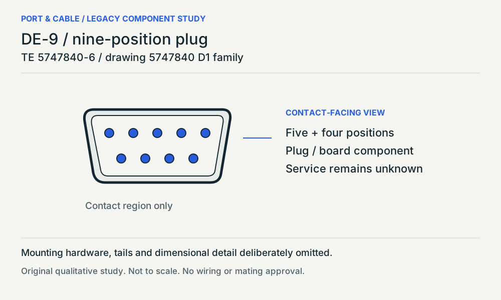
5747840-6 is a PCB component, not a finished serial cable. The source-facing nine-position study omits the optional mounting details and does not establish RS-232 wiring, a null-modem cable or converter support.
Read the evidence and its limits
TE identifies 5747840-6 as a nine-position, two-row plug mounted at right angles to a printed circuit board. C114C
Exact component role and mounting only; this is not an identification of the service on a complete device.
Drawing 5747840 D1 shows five contacts above four in the contact-facing view, separately from the recommended board layout. C114D
Named drawing family only. Pin numbers, dimensions, plating, optional mounting hardware and electrical assignments are not reproduced.
P115 / DB25 D-sub connector
The same form is not the same equipment connection.
Right-angle board receptacle / hardware omitted · Source, view and omissions (private workspace)
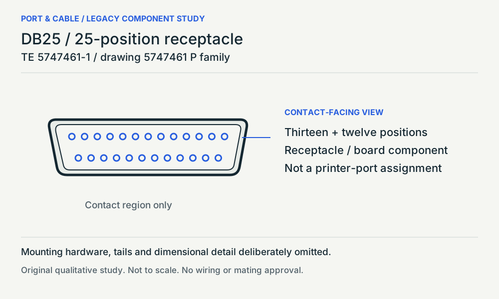
This named receptacle and its family drawing provide a contact-pattern example, not a printer, serial or SCSI assignment. The product page labels the part obsolete; neither this reference nor its drawing recommends a replacement. Conflicting shell-material fields remain unresolved.
Read the evidence and its limits
TE identifies 5747461-1 as a twenty-five-position, two-row right-angle board receptacle; the inspected page labels the part obsolete. C115C
Observed named-component identity and lifecycle label only. No current replacement, material resolution or equipment protocol is inferred.
Drawing 5747461 P shows a thirteen-plus-twelve contact-facing pattern separately from its recommended printed-circuit-board mounting view. C115D
Source-facing family view. The -1 hole variant is distinguished in the table; optional screwlocks are not attributed to that variant. No numbering, footprint dimensions or service mapping entered.
P108 / 6-pin Mini-DIN (PS/2 form)
A six-position Mini-DIN is not proof of PS/2.
Right-angle PCB socket / non-shielded series · Source, view and omissions (private workspace)
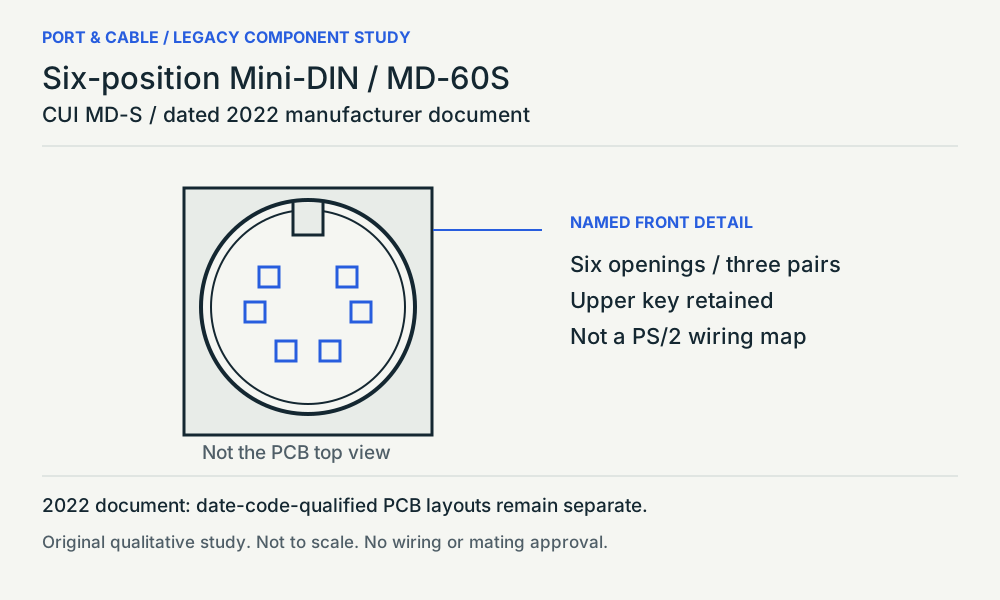
The MD-60S study follows a dated component drawing. The front view helps recognition; date-code-specific PCB layouts do not establish interchangeable footprints. Use the equipment manual to identify keyboard, mouse or another service.
Read the evidence and its limits
The MD-S datasheet identifies option 60 as six pins and describes the series as non-shielded, right-angle PCB mount. C108C
MD-60S in the dated 2022 manufacturer document only; not all six-pin Mini-DIN parts and not a PS/2 interface specification.
The MD-60S detail shows three pairs of contact openings. Its PCB-layout drawings are separately qualified by date codes before and after 03/03/2022. C108D
Front recognition versus board footprint in the 2022 sheet. No equivalence of earlier/later footprints, contact numbering or electrical function is established.
P210 / 8-pin Mini-DIN connector
Eight positions still need an equipment identity.
Right-angle PCB socket / non-shielded series · Source, view and omissions (private workspace)
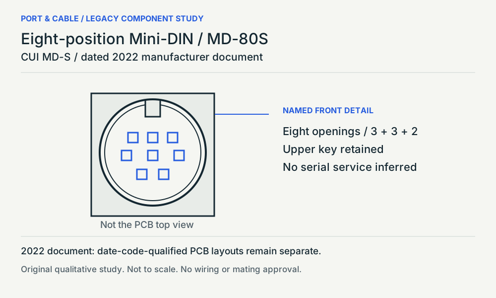
MD-80S supplies a dated eight-contact component example. Its front detail is not the board-footprint view. Contact count does not assign serial or A/V service, identify a compatible adapter or establish a current replacement part.
Read the evidence and its limits
The MD-S datasheet identifies option 80 as eight pins within its non-shielded, right-angle PCB component series. C210B
MD-80S in the dated manufacturer document only; no current-production, serial-port or adapter claim.
The named MD-80S front detail shows eight contact openings in groups of three, three and two; its PCB-layout views carry separate date-code qualifications. C210C
Source-facing component recognition only. The PCB top view is not reused as a mating face, and no universal signal map or replacement footprint is supplied.
03 / WHAT ARE YOU TRYING TO DO?
The next document depends on the job.
Identify an unknown port
Keep a straight-on view, the device model and the label beside the opening together. Compare the family and contact pattern here; then locate that model’s connector description.
Choose a cable or adapter
Find the documented interface at both ends and the required cable or converter. A shell-changing accessory does not establish a supported signal path, wiring arrangement or driver.
Identify a replacement component
Match the exact manufacturer part, revision, mounting and termination documentation. The MD-S sheet explicitly separates PCB layouts by date code; a similar front view is not a footprint approval.
Read the evidence and its limits
The MD-60S detail shows three pairs of contact openings. Its PCB-layout drawings are separately qualified by date codes before and after 03/03/2022. C108D
Front recognition versus board footprint in the 2022 sheet. No equivalence of earlier/later footprints, contact numbering or electrical function is established.
The named MD-80S front detail shows eight contact openings in groups of three, three and two; its PCB-layout views carry separate date-code qualifications. C210C
Source-facing component recognition only. The PCB top view is not reused as a mating face, and no universal signal map or replacement footprint is supplied.
TE identifies 5747461-1 as a twenty-five-position, two-row right-angle board receptacle; the inspected page labels the part obsolete. C115C
Observed named-component identity and lifecycle label only. No current replacement, material resolution or equipment protocol is inferred.
Read a drawing without reversing it
Keep the view label and page locator with every observation. This guide deliberately omits pin numbering, rear views and unobserved counterparts rather than guessing an orientation.
04 / COMMON QUESTIONS
What the outline cannot decide.
CHECK 01
Does a nine-position shell establish RS-232?
No equipment service is established by a component drawing. Compare the two-row form, then obtain the model-specific interface and cable documentation. A passive shell adapter does not prove signal conversion.
Read the evidence and its limits
TE identifies 5747840-6 as a nine-position, two-row plug mounted at right angles to a printed circuit board. C114C
Exact component role and mounting only; this is not an identification of the service on a complete device.
Drawing 5747840 D1 shows five contacts above four in the contact-facing view, separately from the recommended board layout. C114D
Named drawing family only. Pin numbers, dimensions, plating, optional mounting hardware and electrical assignments are not reproduced.
CHECK 02
Is a DB25 necessarily a printer connection?
Treat the exact service as unresolved until the equipment documentation identifies it. This named board receptacle establishes a component example, not the wiring of an installed printer, serial or SCSI port.
Read the evidence and its limits
TE identifies 5747461-1 as a twenty-five-position, two-row right-angle board receptacle; the inspected page labels the part obsolete. C115C
Observed named-component identity and lifecycle label only. No current replacement, material resolution or equipment protocol is inferred.
Drawing 5747461 P shows a thirteen-plus-twelve contact-facing pattern separately from its recommended printed-circuit-board mounting view. C115D
Source-facing family view. The -1 hole variant is distinguished in the table; optional screwlocks are not attributed to that variant. No numbering, footprint dimensions or service mapping entered.
CHECK 03
Does every six-pin Mini-DIN part support PS/2?
The MD-60S source describes a component, not a computer interface implementation. Check the equipment model and port label; do not infer keyboard or mouse service from shape or color.
Read the evidence and its limits
The MD-S datasheet identifies option 60 as six pins and describes the series as non-shielded, right-angle PCB mount. C108C
MD-60S in the dated 2022 manufacturer document only; not all six-pin Mini-DIN parts and not a PS/2 interface specification.
The MD-60S detail shows three pairs of contact openings. Its PCB-layout drawings are separately qualified by date codes before and after 03/03/2022. C108D
Front recognition versus board footprint in the 2022 sheet. No equivalence of earlier/later footprints, contact numbering or electrical function is established.
CHECK 04
Is eight-pin Mini-DIN just a PS/2 variant?
The MD-80S source documents a different contact pattern, not a PS/2 substitute. Do not select a cable by circular outline, contact count or visual resemblance alone.
Read the evidence and its limits
The MD-S datasheet identifies option 80 as eight pins within its non-shielded, right-angle PCB component series. C210B
MD-80S in the dated manufacturer document only; no current-production, serial-port or adapter claim.
The named MD-80S front detail shows eight contact openings in groups of three, three and two; its PCB-layout views carry separate date-code qualifications. C210C
Source-facing component recognition only. The PCB top view is not reused as a mating face, and no universal signal map or replacement footprint is supplied.
CHECK 05
Is the PCB top view the mating-face view?
Keep the drawing view label with the observation. These sheets separately show the contact-facing component and board layout; neither page position nor an assumed mirror image establishes the correct view.
Read the evidence and its limits
Drawing 5747840 D1 shows five contacts above four in the contact-facing view, separately from the recommended board layout. C114D
Named drawing family only. Pin numbers, dimensions, plating, optional mounting hardware and electrical assignments are not reproduced.
Drawing 5747461 P shows a thirteen-plus-twelve contact-facing pattern separately from its recommended printed-circuit-board mounting view. C115D
Source-facing family view. The -1 hole variant is distinguished in the table; optional screwlocks are not attributed to that variant. No numbering, footprint dimensions or service mapping entered.
The MD-60S detail shows three pairs of contact openings. Its PCB-layout drawings are separately qualified by date codes before and after 03/03/2022. C108D
Front recognition versus board footprint in the 2022 sheet. No equivalence of earlier/later footprints, contact numbering or electrical function is established.
The named MD-80S front detail shows eight contact openings in groups of three, three and two; its PCB-layout views carry separate date-code qualifications. C210C
Source-facing component recognition only. The PCB top view is not reused as a mating face, and no universal signal map or replacement footprint is supplied.
CHECK 06
Does a matching face make a replacement drop-in?
No. The MD-S sheet distinguishes PCB layouts by date code, and the named TE DB25 page labels its part obsolete. Obtain an exact supported replacement and revision match; this recognition reference does not certify either.
Read the evidence and its limits
The MD-60S detail shows three pairs of contact openings. Its PCB-layout drawings are separately qualified by date codes before and after 03/03/2022. C108D
Front recognition versus board footprint in the 2022 sheet. No equivalence of earlier/later footprints, contact numbering or electrical function is established.
The named MD-80S front detail shows eight contact openings in groups of three, three and two; its PCB-layout views carry separate date-code qualifications. C210C
Source-facing component recognition only. The PCB top view is not reused as a mating face, and no universal signal map or replacement footprint is supplied.
TE identifies 5747461-1 as a twenty-five-position, two-row right-angle board receptacle; the inspected page labels the part obsolete. C115C
Observed named-component identity and lifecycle label only. No current replacement, material resolution or equipment protocol is inferred.
A COMPACT REFERENCE TO KEEP
Three pages. The source stays attached.
Letter PDF (legacy download held for current evidence review). Current focused printable references · A4 PDF (legacy download held for current evidence review). Current focused printable references
D-sub patterns, Mini-DIN front details, view and replacement cautions, and linked source locators. Original review-edition PDF—not wiring or repair instructions.