FIELD GUIDESource-led reference

P115 / Legacy computer / Connector

DB25 D-sub connector

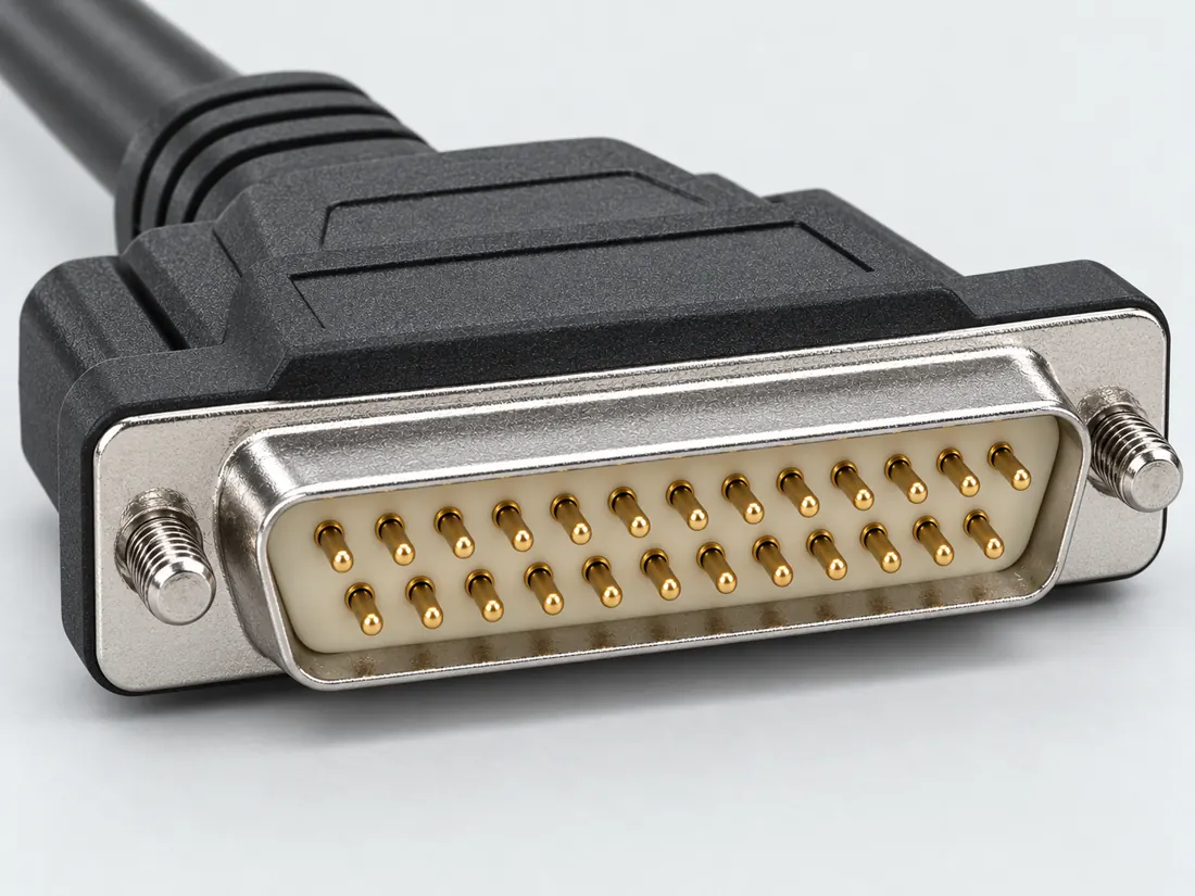
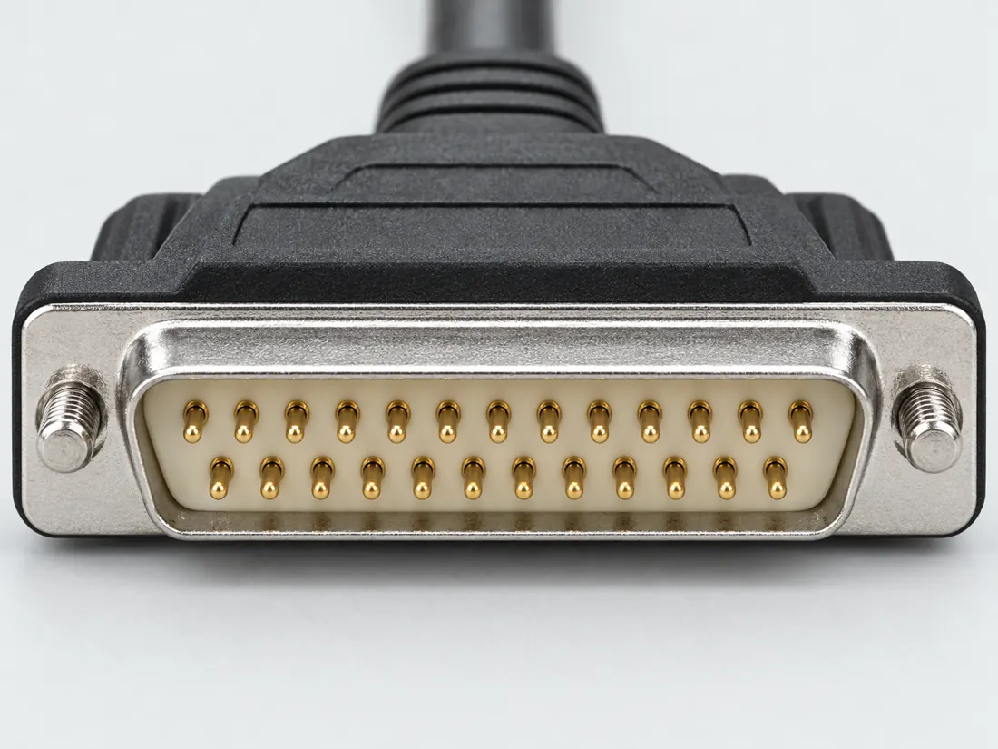
A two-row, twenty-five-position D-sub can appear in parallel, serial and legacy SCSI applications.

Also called 25 pin parallel 25 pin serial DB-25 SCSI DB25

The same shell can carry unrelated interfaces.

Look for

Compare the 13-plus-12 position layout and then read the port label. A broad D-shaped outline is not enough.

Claim inspection dates: 2026-10-03, 2026-10-13 · Independent review pending

Image inspection / P115

See the view. Check its scope.

1 registered view for this reference. Different part examples are not automatically mates; all remain not to scale and independently unapproved.

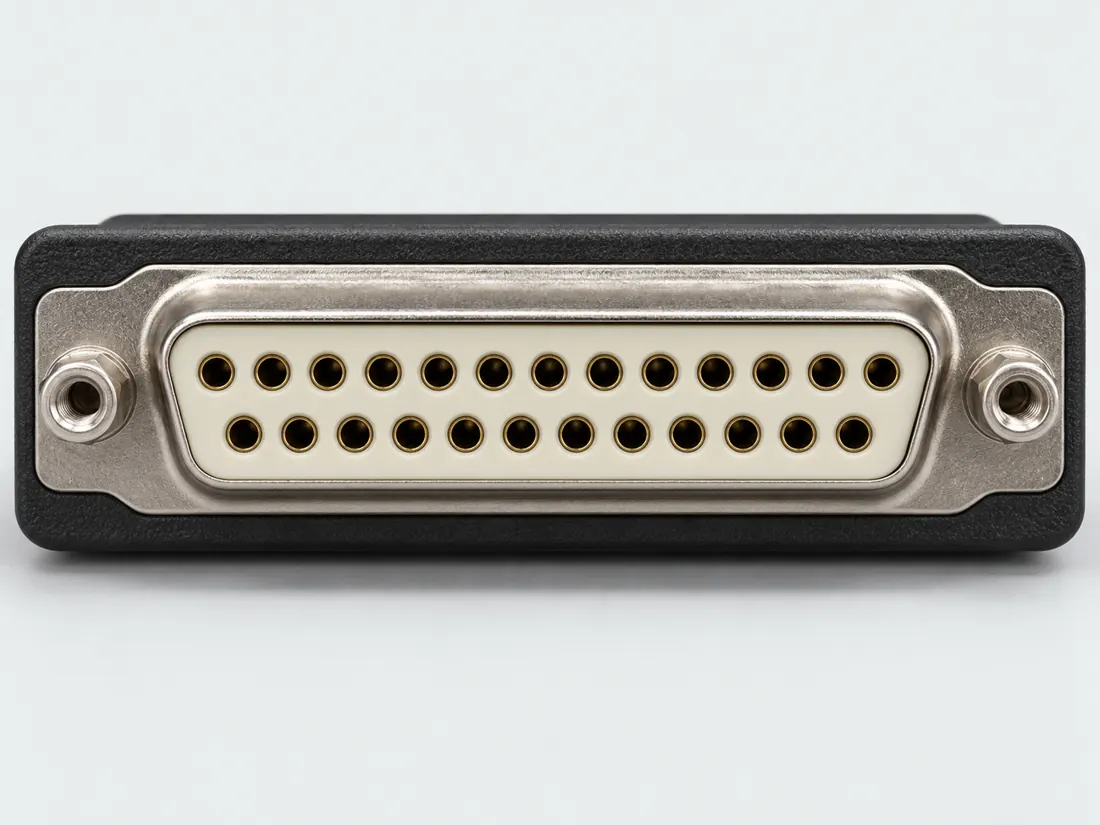
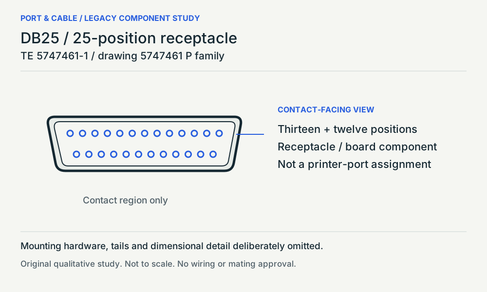
DB25 / 25-position receptacle. Contact-facing view / source longer row above. Two rows: thirteen positions above twelve; Board layout is a separate drawing view; Optional hardware and contact numbering omitted. Original qualitative study, not a pinout. (private workspace)

P115 / Source-observed physical study

DB25 / 25-position receptacle

TE 5747461-1 / drawing 5747461 P family

Contact-facing view / source longer row above · Device receptacle

Not to scale. Technical and rights review pending.

Inspect view & provenance (private workspace)
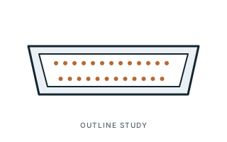
Inspect the illustrationUnnumbered face-pattern sketch · larger view & look-alikes
DB25 D-sub connector — unnumbered face-pattern sketch; role not specified; original, not-to-scale identification schematic; drawing review pending
View Unnumbered face-pattern sketchDepiction Role not specifiedNot to scale · independent drawing review pending

Read the view

Broad D-shaped outline and two rows

The sketch places one row above the other. No solder-side orientation, wiring order or mating approval is supplied.

About the marks: The diagram is not a pinout or a guarantee of actual populated contacts.

What it cannot establish: The same DB25 family name can accompany different device interfaces; the equipment documentation controls.

Enlargement changes display size only. It does not reveal measured geometry, a pin assignment or an approved mating combination.

Compare a likely look-alike

Read the underlying references: S092. Artwork interpretation remains review-pending.

How to read connector illustrations →

The useful distinction

Recognize it. Then verify it.

A two-row, twenty-five-position D-sub can appear in parallel, serial and legacy SCSI applications. [C115A]

The guide lists parallel, RS-232 and SCSI uses of the same form. [C115B]

TE identifies 5747461-1 as a twenty-five-position, two-row right-angle board receptacle; the inspected page labels the part obsolete. [C115C]

Drawing 5747461 P shows a thirteen-plus-twelve contact-facing pattern separately from its recommended printed-circuit-board mounting view. [C115D]

Source-scoped identification facts

Each value retains its exact example, role and measurement axis. Facts from different parts must not be combined into an invented component.

Documented examples; not a mating drawing or compatibility approval
Nominal contacts25S092Twenty-five nominal positions; an actual connector may omit some populated contacts.
Positions / cavity span5 (Claim C115C)S627Recorded source-scoped values; named examples do not describe every family variant or establish compatibility. Observed named-component identity and lifecycle label only. No current replacement, material resolution or equipment protocol is inferred.
Contact rows2 (Claim C115C); 2 (5747461-1)S627 · S627Named source examples retain separate role, part, view and axis limits; values are not a universal family specification. TE identifies 5747461-1 as a twenty-five-position, two-row right-angle board receptacle; the inspected page labels the part obsolete. | Observed named-component identity and lifecycle label only. No current replacement, material resolution or equipment protocol is inferred. 5747461-1. Documented role: socket. TE currently labels this exact part obsolete. No universal DB25 dimensions or pinout inferred.
Contact pitch2.74 mm centerline (5747461-1)S627Named source examples retain separate role, part, view and axis limits; values are not a universal family specification. 5747461-1. Documented role: socket. TE currently labels this exact part obsolete. No universal DB25 dimensions or pinout inferred.
Dimensions / axis2.84 mm row-to-row spacing (5747461-1); 3.18 mm termination post/tail length (5747461-1)S627Named source examples retain separate role, part, view and axis limits; values are not a universal family specification. 5747461-1. Documented role: socket. TE currently labels this exact part obsolete. No universal DB25 dimensions or pinout inferred.
Connector rolesocket (5747461-1)S627Named source examples retain separate role, part, view and axis limits; values are not a universal family specification. 5747461-1. Documented role: socket. TE currently labels this exact part obsolete. No universal DB25 dimensions or pinout inferred.
Mountingboard (Claim C115C)S627Recorded source-scoped values; named examples do not describe every family variant or establish compatibility. Observed named-component identity and lifecycle label only. No current replacement, material resolution or equipment protocol is inferred.
ManufacturerTE Connectivity (5747461-1)S627Named source examples retain separate role, part, view and axis limits; values are not a universal family specification. 5747461-1. Documented role: socket. TE currently labels this exact part obsolete. No universal DB25 dimensions or pinout inferred.
SeriesAMPLIMITE HD-20 (5747461-1)S627Named source examples retain separate role, part, view and axis limits; values are not a universal family specification. 5747461-1. Documented role: socket. TE currently labels this exact part obsolete. No universal DB25 dimensions or pinout inferred.
Exact part / implementation5747461-1 (5747461-1)S627Named source examples retain separate role, part, view and axis limits; values are not a universal family specification. 5747461-1. Documented role: socket. TE currently labels this exact part obsolete. No universal DB25 dimensions or pinout inferred.

Not recorded: Populated contacts, Contact gender / arrangement, Coupling / latch, Keying / polarization, Shell / form, Recorded markings, View convention. Unknown fields stay unknown; illustrations supply no measurements or pin assignments.

Recorded variant and source limits
  • Check the exact device manual before wiring or applying power.
  • IBM PC AT Serial/Parallel Adapter parallel port (host side), DB-25 female: IBM figure shows the adapter's 25-pin connector (1-13 / 14-25); directions as drawn relative to the adapter.
  • IBM PS/2 parallel port (Type 1), 25-pin D-shell: IBM drawing numbers 13...1 on the top row and 25...14 on the bottom row (receptacle face as drawn).
  • IBM PS/2 serial port (DTE), 25-pin D-shell: IBM drawing numbers 1...13 top row, 14...25 bottom row (as drawn).
  • Apple Macintosh Plus SCSI port, DB-25 (non-RS-232 use): Pin numbers from Apple's table; no face view.
  • IBM PS/2 Model 25 parallel port (PC host, female DB25): D-sub contact numbers 1-25 as moulded. IBM Model 25 drawings are 'viewed from the rear of the system unit': serial shows pin 1 top-left (pin face), parallel shows pin 1 top-right (socket face).
  • IBM PS/2 Model 25 serial port (RS-232 DTE, male DB25): D-sub contact numbers 1-25 as moulded. IBM Model 25 drawings are 'viewed from the rear of the system unit': serial shows pin 1 top-left (pin face), parallel shows pin 1 top-right (socket face).
  • SMSC FDC37C669 parallel-port host connector, SPP/EPP/ECP signal names: D-sub contact numbers 1-25 as moulded. IBM Model 25 drawings are 'viewed from the rear of the system unit': serial shows pin 1 top-left (pin face), parallel shows pin 1 top-right (socket face).
Report a correction to these facts →

Bounded facts, visible unknowns

Specifications and limits

DB25 D-sub connector facts and limitations
Documented identificationThe DB25 form has twenty-five nominal positions arranged in rows of thirteen and twelve. [C115A]
Important distinctionThe guide lists parallel, RS-232 and SCSI uses of the same form. [C115B]
Source-scoped component observationTE identifies 5747461-1 as a twenty-five-position, two-row right-angle board receptacle; the inspected page labels the part obsolete. [C115C]
Source-scoped component observationDrawing 5747461 P shows a thirteen-plus-twelve contact-facing pattern separately from its recommended printed-circuit-board mounting view. [C115D]
Mechanical dimensionsNo independently approved mechanical dimensions. Do not use this record for fabrication or fit testing.
Engineering pinoutSource-checked engineering profile available; independent review pending. Open engineering profile →
Verified device listNot included. Check exact device and accessory documentation.
A boundary, not an omission to guess around.

Record the exact device model and the label beside the port. Obtain its manual and the accessory documentation. Keep unknown properties unknown instead of filling them from a visually similar item.

Before you connect

What to check

  1. Identify whether the equipment documents parallel, serial, SCSI or another application.
  2. Verify the required cable wiring before purchase.
  3. Do not use a passive shape adapter as evidence of protocol conversion.
Trace a supported connection class →

Pins & wiring

Pinout

Choose the exact wiring. Pin numbers follow its stated view; a schematic does not establish physical positions. Check your exact device before wiring.

What the status labels mean
Confirmed
Recorded research passes agree within this variant; this is not independent human review or hardware validation.
Single source
Only one underlying document, or one pass, supports this assignment.
Device-specific
Supported for the named equipment or wiring only. Check your device’s manual.
Unverified
Missing or conflicting evidence. Do not wire from this row.
Not connected
The source explicitly says NC, no contact or no pin for this wiring.
Wiring variant

IBM PC AT Serial/Parallel Adapter parallel port (host side), DB-25 female

Device-specific wiring. Check your device’s manual before connecting or applying power.

View and evidence limits

IBM figure shows the adapter's 25-pin connector (1-13 / 14-25); directions as drawn relative to the adapter.

  • P115 DB25 — **Agree** on the PC parallel port (1 −Strobe, 2–9 data 0–7, 10 −ACK, 11 Busy, 12 PE, 13 Select, 14 −Auto Feed, 15 −Error, 16 −Init, 17 −Select In, 18–25 ground) and the IBM PS/2 serial port on all main signals — **One documented difference: serial pin 11.** A's PS/2 Hardware Interface reference says not connected; B's PS/2 Model 25 reference says "tied to line 20" (DTR). These are different IBM documents and models, so record pin 11 as model-specific, not a conflict to resolve. B's SMSC FDC37C669 signal names stay unverified because that datasheet doesn't tie them to a DB25. A adds the Mac Plus SCSI port as an unrelated DB25 use.
  • TIA-232-F is paywalled; only the IBM PS/2 DTE subset is verified.
  • IEEE 1284 is paywalled; host parallel rows rely on IBM.
  • Sun/Apple serial, audio multicore (AES59/Tascam), and other uses not established.
DB25 D-sub (PC parallel port, RS-232 and other uses) engineering referenceIBM figure shows the adapter's 25-pin connector (1-13 / 14-25); directions as drawn relative to the adapter.SCHEMATIC · physical positions unconfirmedNot to scale · check the named wiring and device manual1: -Strobe (device_specific)12: Data Bit 0 (device_specific)23: Data Bit 1 (device_specific)34: Data Bit 2 (device_specific)45: Data Bit 3 (device_specific)56: Data Bit 4 (device_specific)67: Data Bit 5 (device_specific)78: Data Bit 6 (device_specific)89: Data Bit 7 (device_specific)910: -ACK (device_specific)1011: BUSY (device_specific)1112: PE (device_specific)1213: SLCT (device_specific)1314: -AUTO FEED XT (device_specific)1415: -ERROR (device_specific)1516: -INIT (device_specific)1617: -SLCT IN (device_specific)1718: Ground (device_specific)1819: Ground (device_specific)1920: Ground (device_specific)2021: Ground (device_specific)2122: Ground (device_specific)2223: Ground (device_specific)2324: Ground (device_specific)2425: Ground (device_specific)25powergrounddataConfigshieldNCUnknown
Schematic only · physical contact positions unconfirmed. Original drawing · not to scale. Scroll sideways if needed.
IBM PC AT Serial/Parallel Adapter parallel port (host side), DB-25 female — source-scoped contact map
PinSignalWhat it doesStatus
1-StrobeControl, detection or configuration connection; check the source and device.Device-specific
Sources
2Data Bit 0Signal conductor. Pair, polarity and direction follow this named wiring.Device-specific
Sources
3Data Bit 1Signal conductor. Pair, polarity and direction follow this named wiring.Device-specific
Sources
4Data Bit 2Signal conductor. Pair, polarity and direction follow this named wiring.Device-specific
Sources
5Data Bit 3Signal conductor. Pair, polarity and direction follow this named wiring.Device-specific
Sources
6Data Bit 4Signal conductor. Pair, polarity and direction follow this named wiring.Device-specific
Sources
7Data Bit 5Signal conductor. Pair, polarity and direction follow this named wiring.Device-specific
Sources
8Data Bit 6Signal conductor. Pair, polarity and direction follow this named wiring.Device-specific
Sources
9Data Bit 7Signal conductor. Pair, polarity and direction follow this named wiring.Device-specific
Sources
10-ACKControl, detection or configuration connection; check the source and device.Device-specific
Sources
11BUSYControl, detection or configuration connection; check the source and device.Device-specific
Sources
12PEControl, detection or configuration connection; check the source and device.Device-specific
Sources
13SLCTControl, detection or configuration connection; check the source and device.Device-specific
Sources
14-AUTO FEED XTControl, detection or configuration connection; check the source and device.Device-specific
Sources
15-ERRORControl, detection or configuration connection; check the source and device.Device-specific
Sources
16-INITControl, detection or configuration connection; check the source and device.Device-specific
Sources
17-SLCT INControl, detection or configuration connection; check the source and device.Device-specific
Sources
18GroundGround reference and return.Device-specific
Sources
19GroundGround reference and return.Device-specific
Sources
20GroundGround reference and return.Device-specific
Sources
21GroundGround reference and return.Device-specific
Sources
22GroundGround reference and return.Device-specific
Sources
23GroundGround reference and return.Device-specific
Sources
24GroundGround reference and return.Device-specific
Sources
25GroundGround reference and return.Device-specific
Sources
Sources (1)

IBM PS/2 parallel port (Type 1), 25-pin D-shell

Device-specific wiring. Check your device’s manual before connecting or applying power.

View and evidence limits

IBM drawing numbers 13...1 on the top row and 25...14 on the bottom row (receptacle face as drawn).

  • P115 DB25 — **Agree** on the PC parallel port (1 −Strobe, 2–9 data 0–7, 10 −ACK, 11 Busy, 12 PE, 13 Select, 14 −Auto Feed, 15 −Error, 16 −Init, 17 −Select In, 18–25 ground) and the IBM PS/2 serial port on all main signals — **One documented difference: serial pin 11.** A's PS/2 Hardware Interface reference says not connected; B's PS/2 Model 25 reference says "tied to line 20" (DTR). These are different IBM documents and models, so record pin 11 as model-specific, not a conflict to resolve. B's SMSC FDC37C669 signal names stay unverified because that datasheet doesn't tie them to a DB25. A adds the Mac Plus SCSI port as an unrelated DB25 use.
  • I/O column: pins 1-9 'I/O', 10-13 'I', 14/16/17 'O', 15 'I', 18-25 'NA'. Data lines are bidirectional in extended mode.
  • TIA-232-F is paywalled; only the IBM PS/2 DTE subset is verified.
  • IEEE 1284 is paywalled; host parallel rows rely on IBM.
  • Sun/Apple serial, audio multicore (AES59/Tascam), and other uses not established.
DB25 D-sub (PC parallel port, RS-232 and other uses) engineering referenceIBM drawing numbers 13...1 on the top row and 25...14 on the bottom row (receptacle face as drawn).SCHEMATIC · physical positions unconfirmedNot to scale · check the named wiring and device manual1: -STROBE (device_specific)12: Data 0 (device_specific)23: Data 1 (device_specific)34: Data 2 (device_specific)45: Data 3 (device_specific)56: Data 4 (device_specific)67: Data 5 (device_specific)78: Data 6 (device_specific)89: Data 7 (device_specific)910: -ACK (device_specific)1011: BUSY (device_specific)1112: PE (device_specific)1213: SLCT (device_specific)1314: -AUTO FD XT (device_specific)1415: -ERROR (device_specific)1516: -INIT (device_specific)1617: -SLCT IN (device_specific)1718: Ground (device_specific)1819: Ground (device_specific)1920: Ground (device_specific)2021: Ground (device_specific)2122: Ground (device_specific)2223: Ground (device_specific)2324: Ground (device_specific)2425: Ground (device_specific)25powergrounddataConfigshieldNCUnknown
Schematic only · physical contact positions unconfirmed. Original drawing · not to scale. Scroll sideways if needed.
IBM PS/2 parallel port (Type 1), 25-pin D-shell — source-scoped contact map
PinSignalWhat it doesStatus
1-STROBEControl, detection or configuration connection; check the source and device.Device-specific
Sources
2Data 0Signal conductor. Pair, polarity and direction follow this named wiring.Device-specific
Sources
3Data 1Signal conductor. Pair, polarity and direction follow this named wiring.Device-specific
Sources
4Data 2Signal conductor. Pair, polarity and direction follow this named wiring.Device-specific
Sources
5Data 3Signal conductor. Pair, polarity and direction follow this named wiring.Device-specific
Sources
6Data 4Signal conductor. Pair, polarity and direction follow this named wiring.Device-specific
Sources
7Data 5Signal conductor. Pair, polarity and direction follow this named wiring.Device-specific
Sources
8Data 6Signal conductor. Pair, polarity and direction follow this named wiring.Device-specific
Sources
9Data 7Signal conductor. Pair, polarity and direction follow this named wiring.Device-specific
Sources
10-ACKControl, detection or configuration connection; check the source and device.Device-specific
Sources
11BUSYControl, detection or configuration connection; check the source and device.Device-specific
Sources
12PEControl, detection or configuration connection; check the source and device.Device-specific
Sources
13SLCTControl, detection or configuration connection; check the source and device.Device-specific
Sources
14-AUTO FD XTControl, detection or configuration connection; check the source and device.Device-specific
Sources
15-ERRORControl, detection or configuration connection; check the source and device.Device-specific
Sources
16-INITControl, detection or configuration connection; check the source and device.Device-specific
Sources
17-SLCT INControl, detection or configuration connection; check the source and device.Device-specific
Sources
18GroundGround reference and return.Device-specific
Sources
19GroundGround reference and return.Device-specific
Sources
20GroundGround reference and return.Device-specific
Sources
21GroundGround reference and return.Device-specific
Sources
22GroundGround reference and return.Device-specific
Sources
23GroundGround reference and return.Device-specific
Sources
24GroundGround reference and return.Device-specific
Sources
25GroundGround reference and return.Device-specific
Sources
Sources (1)

IBM PS/2 serial port (DTE), 25-pin D-shell

Device-specific wiring. Check your device’s manual before connecting or applying power.

View and evidence limits

IBM drawing numbers 1...13 top row, 14...25 bottom row (as drawn).

  • P115 DB25 — **Agree** on the PC parallel port (1 −Strobe, 2–9 data 0–7, 10 −ACK, 11 Busy, 12 PE, 13 Select, 14 −Auto Feed, 15 −Error, 16 −Init, 17 −Select In, 18–25 ground) and the IBM PS/2 serial port on all main signals — **One documented difference: serial pin 11.** A's PS/2 Hardware Interface reference says not connected; B's PS/2 Model 25 reference says "tied to line 20" (DTR). These are different IBM documents and models, so record pin 11 as model-specific, not a conflict to resolve. B's SMSC FDC37C669 signal names stay unverified because that datasheet doesn't tie them to a DB25. A adds the Mac Plus SCSI port as an unrelated DB25 use.
  • IBM: 'standard D-shell connector and pin assignments defined for RS-232C', EIA voltage levels only, no current loop.
  • TIA-232-F is paywalled; only the IBM PS/2 DTE subset is verified.
  • IEEE 1284 is paywalled; host parallel rows rely on IBM.
  • Sun/Apple serial, audio multicore (AES59/Tascam), and other uses not established.
DB25 D-sub (PC parallel port, RS-232 and other uses) engineering referenceIBM drawing numbers 1...13 top row, 14...25 bottom row (as drawn).SCHEMATIC · physical positions unconfirmedNot to scale · check the named wiring and device manual1: Not Connected (not_connected)12: Transmit Data (device_specific)23: Receive Data (device_specific)34: Request to Send (device_specific)45: Clear to Send (device_specific)56: Data Set Ready (device_specific)67: Signal Ground (device_specific)78: Data Carrier Detect (device_specific)89: Not Connected (not_connected)910: Not Connected (not_connected)1011: Not Connected (not_connected)1112: Not Connected (not_connected)1213: Not Connected (not_connected)1314: Not Connected (not_connected)1415: Not Connected (not_connected)1516: Not Connected (not_connected)1617: Not Connected (not_connected)1718: Not Connected (not_connected)1819: Not Connected (not_connected)1920: Data Terminal Ready (device_specific)2021: Not Connected (not_connected)2122: Ring Indicator (device_specific)2223: Not Connected (not_connected)2324: Not Connected (not_connected)2425: Not Connected (not_connected)25powergrounddataConfigshieldNCUnknown
Schematic only · physical contact positions unconfirmed. Original drawing · not to scale. Scroll sideways if needed.
IBM PS/2 serial port (DTE), 25-pin D-shell — source-scoped contact map
PinSignalWhat it doesStatus
1Not ConnectedNot connected or absent in this named wiring.Not connected
Sources
2Transmit DataSignal conductor. Pair, polarity and direction follow this named wiring.Device-specific
Sources
3Receive DataSignal conductor. Pair, polarity and direction follow this named wiring.Device-specific
Sources
4Request to SendControl, detection or configuration connection; check the source and device.Device-specific
Sources
5Clear to SendControl, detection or configuration connection; check the source and device.Device-specific
Sources
6Data Set ReadySignal conductor. Pair, polarity and direction follow this named wiring.Device-specific
Sources
7Signal GroundControl, detection or configuration connection; check the source and device.Device-specific
Sources
8Data Carrier DetectIndicates a detected serial carrier.Device-specific
Sources
9Not ConnectedNot connected or absent in this named wiring.Not connected
Sources
10Not ConnectedNot connected or absent in this named wiring.Not connected
Sources
11Not ConnectedNot connected or absent in this named wiring.Not connected
Sources
12Not ConnectedNot connected or absent in this named wiring.Not connected
Sources
13Not ConnectedNot connected or absent in this named wiring.Not connected
Sources
14Not ConnectedNot connected or absent in this named wiring.Not connected
Sources
15Not ConnectedNot connected or absent in this named wiring.Not connected
Sources
16Not ConnectedNot connected or absent in this named wiring.Not connected
Sources
17Not ConnectedNot connected or absent in this named wiring.Not connected
Sources
18Not ConnectedNot connected or absent in this named wiring.Not connected
Sources
19Not ConnectedNot connected or absent in this named wiring.Not connected
Sources
20Data Terminal ReadySignal conductor. Pair, polarity and direction follow this named wiring.Device-specific
Sources
21Not ConnectedNot connected or absent in this named wiring.Not connected
Sources
22Ring IndicatorControl, detection or configuration connection; check the source and device.Device-specific
Sources
23Not ConnectedNot connected or absent in this named wiring.Not connected
Sources
24Not ConnectedNot connected or absent in this named wiring.Not connected
Sources
25Not ConnectedNot connected or absent in this named wiring.Not connected
Sources
Sources (1)

Apple Macintosh Plus SCSI port, DB-25 (non-RS-232 use)

Device-specific wiring. Check your device’s manual before connecting or applying power.

View and evidence limits

Pin numbers from Apple's table; no face view.

  • P115 DB25 — **Agree** on the PC parallel port (1 −Strobe, 2–9 data 0–7, 10 −ACK, 11 Busy, 12 PE, 13 Select, 14 −Auto Feed, 15 −Error, 16 −Init, 17 −Select In, 18–25 ground) and the IBM PS/2 serial port on all main signals — **One documented difference: serial pin 11.** A's PS/2 Hardware Interface reference says not connected; B's PS/2 Model 25 reference says "tied to line 20" (DTR). These are different IBM documents and models, so record pin 11 as model-specific, not a conflict to resolve. B's SMSC FDC37C669 signal names stay unverified because that datasheet doesn't tie them to a DB25. A adds the Mac Plus SCSI port as an unrelated DB25 use.
  • Included to show that DB-25 carries unrelated interfaces; signals with '-' are active-low.
  • TIA-232-F is paywalled; only the IBM PS/2 DTE subset is verified.
  • IEEE 1284 is paywalled; host parallel rows rely on IBM.
  • Sun/Apple serial, audio multicore (AES59/Tascam), and other uses not established.
DB25 D-sub (PC parallel port, RS-232 and other uses) engineering referencePin numbers from Apple's table; no face view.SCHEMATIC · physical positions unconfirmedNot to scale · check the named wiring and device manual1: REQ- (device_specific)12: MSG- (device_specific)23: I/O- (device_specific)34: RST- (device_specific)45: ACK- (device_specific)56: BSY- (device_specific)67: Ground (device_specific)78: DB0- (device_specific)89: Ground (device_specific)910: DB3- (device_specific)1011: DB5- (device_specific)1112: DB6- (device_specific)1213: DB7- (device_specific)1314: Ground (device_specific)1415: C/D- (device_specific)1516: Ground (device_specific)1617: ATN- (device_specific)1718: Ground (device_specific)1819: SEL- (device_specific)1920: DBP- (device_specific)2021: DB1- (device_specific)2122: DB2- (device_specific)2223: DB4- (device_specific)2324: Ground (device_specific)2425: TPWR (Not connected) (not_connected)25powergrounddataConfigshieldNCUnknown
Schematic only · physical contact positions unconfirmed. Original drawing · not to scale. Scroll sideways if needed.
Apple Macintosh Plus SCSI port, DB-25 (non-RS-232 use) — source-scoped contact map
PinSignalWhat it doesStatus
1REQ-Control, detection or configuration connection; check the source and device.Device-specific
Sources
2MSG-Control, detection or configuration connection; check the source and device.Device-specific
Sources
3I/O-Control, detection or configuration connection; check the source and device.Device-specific
Sources
4RST-Reset control; check active level and the named device.Device-specific
Sources
5ACK-Control, detection or configuration connection; check the source and device.Device-specific
Sources
6BSY-Control, detection or configuration connection; check the source and device.Device-specific
Sources
7GroundGround reference and return.Device-specific
Sources
8DB0-Control, detection or configuration connection; check the source and device.Device-specific
Sources
9GroundGround reference and return.Device-specific
Sources
10DB3-Control, detection or configuration connection; check the source and device.Device-specific
Sources
11DB5-Control, detection or configuration connection; check the source and device.Device-specific
Sources
12DB6-Control, detection or configuration connection; check the source and device.Device-specific
Sources
13DB7-Control, detection or configuration connection; check the source and device.Device-specific
Sources
14GroundGround reference and return.Device-specific
Sources
15C/D-Signal conductor. Pair, polarity and direction follow this named wiring.Device-specific
Sources
16GroundGround reference and return.Device-specific
Sources
17ATN-Control, detection or configuration connection; check the source and device.Device-specific
Sources
18GroundGround reference and return.Device-specific
Sources
19SEL-Control, detection or configuration connection; check the source and device.Device-specific
Sources
20DBP-Control, detection or configuration connection; check the source and device.Device-specific
Sources
21DB1-Control, detection or configuration connection; check the source and device.Device-specific
Sources
22DB2-Control, detection or configuration connection; check the source and device.Device-specific
Sources
23DB4-Control, detection or configuration connection; check the source and device.Device-specific
Sources
24GroundGround reference and return.Device-specific
Sources
25TPWR (Not connected)Not connected or absent in this named wiring.Not connected
Sources
Sources (1)

IBM PS/2 Model 25 parallel port (PC host, female DB25)

Device-specific wiring. Check your device’s manual before connecting or applying power.

View and evidence limits

D-sub contact numbers 1-25 as moulded. IBM Model 25 drawings are 'viewed from the rear of the system unit': serial shows pin 1 top-left (pin face), parallel shows pin 1 top-right (socket face).

  • P115 DB25 — **Agree** on the PC parallel port (1 −Strobe, 2–9 data 0–7, 10 −ACK, 11 Busy, 12 PE, 13 Select, 14 −Auto Feed, 15 −Error, 16 −Init, 17 −Select In, 18–25 ground) and the IBM PS/2 serial port on all main signals — **One documented difference: serial pin 11.** A's PS/2 Hardware Interface reference says not connected; B's PS/2 Model 25 reference says "tied to line 20" (DTR). These are different IBM documents and models, so record pin 11 as model-specific, not a conflict to resolve. B's SMSC FDC37C669 signal names stay unverified because that datasheet doesn't tie them to a DB25. A adds the Mac Plus SCSI port as an unrelated DB25 use.
  • IEEE 1284 is paywalled and was not read; EPP/ECP names come only from the SMSC datasheet table and are not tied to the DB25 shell by that document.
  • TIA-232-F is paywalled and was not read; the serial variant is IBM Model 25 device-specific (only 10 functional pins wired).
  • Mac SCSI (see Apple HW10 Figure 2, not recorded), DCE/modem side, synchronous RS-232 pins and other uses were not recorded.
DB25 D-sub (PC parallel port, RS-232 and other uses) engineering referenceD-sub contact numbers 1-25 as moulded. IBM Model 25 drawings are 'viewed from the rear of the system unit': serial shows pin 1 top-left (pin face), parallel shows pin 1 top-right (socket face).SCHEMATIC · physical positions unconfirmedNot to scale · check the named wiring and device manual1: -Strobe (device_specific)12: D0 (device_specific)23: D1 (device_specific)34: D2 (device_specific)45: D3 (device_specific)56: D4 (device_specific)67: D5 (device_specific)78: D6 (device_specific)89: D7 (device_specific)910: -ACK (device_specific)1011: Busy (device_specific)1112: PE (device_specific)1213: Slct (device_specific)1314: -Auto FD XT (device_specific)1415: -Error (device_specific)1516: -Init (device_specific)1617: -Slct In (device_specific)1718: Ground (device_specific)1819: Ground (device_specific)1920: Ground (device_specific)2021: Ground (device_specific)2122: Ground (device_specific)2223: Ground (device_specific)2324: Ground (device_specific)2425: Ground (device_specific)25powergrounddataConfigshieldNCUnknown
Schematic only · physical contact positions unconfirmed. Original drawing · not to scale. Scroll sideways if needed.
IBM PS/2 Model 25 parallel port (PC host, female DB25) — source-scoped contact map
PinSignalWhat it doesStatus
1-StrobeControl, detection or configuration connection; check the source and device.Device-specific
Sources
2D0Control, detection or configuration connection; check the source and device.Device-specific
Sources
3D1Control, detection or configuration connection; check the source and device.Device-specific
Sources
4D2Control, detection or configuration connection; check the source and device.Device-specific
Sources
5D3Control, detection or configuration connection; check the source and device.Device-specific
Sources
6D4Control, detection or configuration connection; check the source and device.Device-specific
Sources
7D5Control, detection or configuration connection; check the source and device.Device-specific
Sources
8D6Control, detection or configuration connection; check the source and device.Device-specific
Sources
9D7Control, detection or configuration connection; check the source and device.Device-specific
Sources
10-ACKControl, detection or configuration connection; check the source and device.Device-specific
Sources
11BusyControl, detection or configuration connection; check the source and device.Device-specific
Sources
12PEControl, detection or configuration connection; check the source and device.Device-specific
Sources
13SlctControl, detection or configuration connection; check the source and device.Device-specific
Sources
14-Auto FD XTControl, detection or configuration connection; check the source and device.Device-specific
Sources
15-ErrorControl, detection or configuration connection; check the source and device.Device-specific
Sources
16-InitControl, detection or configuration connection; check the source and device.Device-specific
Sources
17-Slct InControl, detection or configuration connection; check the source and device.Device-specific
Sources
18GroundGround reference and return.Device-specific
Sources
19GroundGround reference and return.Device-specific
Sources
20GroundGround reference and return.Device-specific
Sources
21GroundGround reference and return.Device-specific
Sources
22GroundGround reference and return.Device-specific
Sources
23GroundGround reference and return.Device-specific
Sources
24GroundGround reference and return.Device-specific
Sources
25GroundGround reference and return.Device-specific
Sources
Sources (1)

IBM PS/2 Model 25 serial port (RS-232 DTE, male DB25)

Device-specific wiring. Check your device’s manual before connecting or applying power.

View and evidence limits

D-sub contact numbers 1-25 as moulded. IBM Model 25 drawings are 'viewed from the rear of the system unit': serial shows pin 1 top-left (pin face), parallel shows pin 1 top-right (socket face).

  • P115 DB25 — **Agree** on the PC parallel port (1 −Strobe, 2–9 data 0–7, 10 −ACK, 11 Busy, 12 PE, 13 Select, 14 −Auto Feed, 15 −Error, 16 −Init, 17 −Select In, 18–25 ground) and the IBM PS/2 serial port on all main signals — **One documented difference: serial pin 11.** A's PS/2 Hardware Interface reference says not connected; B's PS/2 Model 25 reference says "tied to line 20" (DTR). These are different IBM documents and models, so record pin 11 as model-specific, not a conflict to resolve. B's SMSC FDC37C669 signal names stay unverified because that datasheet doesn't tie them to a DB25. A adds the Mac Plus SCSI port as an unrelated DB25 use.
  • IEEE 1284 is paywalled and was not read; EPP/ECP names come only from the SMSC datasheet table and are not tied to the DB25 shell by that document.
  • TIA-232-F is paywalled and was not read; the serial variant is IBM Model 25 device-specific (only 10 functional pins wired).
  • Mac SCSI (see Apple HW10 Figure 2, not recorded), DCE/modem side, synchronous RS-232 pins and other uses were not recorded.
DB25 D-sub (PC parallel port, RS-232 and other uses) engineering referenceD-sub contact numbers 1-25 as moulded. IBM Model 25 drawings are 'viewed from the rear of the system unit': serial shows pin 1 top-left (pin face), parallel shows pin 1 top-right (socket face).SCHEMATIC · physical positions unconfirmedNot to scale · check the named wiring and device manual1: Not Connected (not_connected)12: Transmit Data (device_specific)23: Receive Data (device_specific)34: -Request to Send (device_specific)45: -Clear to Send (device_specific)56: -Data Set Ready (device_specific)67: Signal Ground (device_specific)78: -RLSD (device_specific)89: Not Connected (not_connected)910: Not Connected (not_connected)1011: Tied to line 20 (device_specific)1112: Not Connected (not_connected)1213: Not Connected (not_connected)1314: Not Connected (not_connected)1415: Not Connected (not_connected)1516: Not Connected (not_connected)1617: Not Connected (not_connected)1718: Not Connected (not_connected)1819: Not Connected (not_connected)1920: -Data Terminal Ready (device_specific)2021: Not Connected (not_connected)2122: -Ring Indicate (device_specific)2223: Not Connected (not_connected)2324: Not Connected (not_connected)2425: Not Connected (not_connected)25powergrounddataConfigshieldNCUnknown
Schematic only · physical contact positions unconfirmed. Original drawing · not to scale. Scroll sideways if needed.
IBM PS/2 Model 25 serial port (RS-232 DTE, male DB25) — source-scoped contact map
PinSignalWhat it doesStatus
1Not ConnectedNot connected or absent in this named wiring.Not connected
Sources
2Transmit DataSignal conductor. Pair, polarity and direction follow this named wiring.Device-specific
Sources
3Receive DataSignal conductor. Pair, polarity and direction follow this named wiring.Device-specific
Sources
4-Request to SendControl, detection or configuration connection; check the source and device.Device-specific
Sources
5-Clear to SendControl, detection or configuration connection; check the source and device.Device-specific
Sources
6-Data Set ReadySignal conductor. Pair, polarity and direction follow this named wiring.Device-specific
Sources
7Signal GroundControl, detection or configuration connection; check the source and device.Device-specific
Sources
8-RLSDControl, detection or configuration connection; check the source and device.Device-specific
Sources
9Not ConnectedNot connected or absent in this named wiring.Not connected
Sources
10Not ConnectedNot connected or absent in this named wiring.Not connected
Sources
11Tied to line 20Control, detection or configuration connection; check the source and device.Device-specific
Sources
12Not ConnectedNot connected or absent in this named wiring.Not connected
Sources
13Not ConnectedNot connected or absent in this named wiring.Not connected
Sources
14Not ConnectedNot connected or absent in this named wiring.Not connected
Sources
15Not ConnectedNot connected or absent in this named wiring.Not connected
Sources
16Not ConnectedNot connected or absent in this named wiring.Not connected
Sources
17Not ConnectedNot connected or absent in this named wiring.Not connected
Sources
18Not ConnectedNot connected or absent in this named wiring.Not connected
Sources
19Not ConnectedNot connected or absent in this named wiring.Not connected
Sources
20-Data Terminal ReadySignal conductor. Pair, polarity and direction follow this named wiring.Device-specific
Sources
21Not ConnectedNot connected or absent in this named wiring.Not connected
Sources
22-Ring IndicateControl, detection or configuration connection; check the source and device.Device-specific
Sources
23Not ConnectedNot connected or absent in this named wiring.Not connected
Sources
24Not ConnectedNot connected or absent in this named wiring.Not connected
Sources
25Not ConnectedNot connected or absent in this named wiring.Not connected
Sources
Sources (1)

SMSC FDC37C669 parallel-port host connector, SPP/EPP/ECP signal names

Device-specific wiring. Check your device’s manual before connecting or applying power.

View and evidence limits

SMSC Table36 HOSTCONNECTOR numbers1-17 only. This document does not establish DB25 shell identity, pins18-25, or a physical mating-face/rear view; IBM Model25 drawings are a different implementation.

  • P115 DB25 — **Agree** on the PC parallel port (1 −Strobe, 2–9 data 0–7, 10 −ACK, 11 Busy, 12 PE, 13 Select, 14 −Auto Feed, 15 −Error, 16 −Init, 17 −Select In, 18–25 ground) and the IBM PS/2 serial port on all main signals — **One documented difference: serial pin 11.** A's PS/2 Hardware Interface reference says not connected; B's PS/2 Model 25 reference says "tied to line 20" (DTR). These are different IBM documents and models, so record pin 11 as model-specific, not a conflict to resolve. B's SMSC FDC37C669 signal names stay unverified because that datasheet doesn't tie them to a DB25. A adds the Mac Plus SCSI port as an unrelated DB25 use.
  • Table 36 numbers 'HOST CONNECTOR' pins 1-17 but does not name the shell (DB25) or list pins 18-25; rows are therefore unverified for this connector record.
  • IEEE 1284 is paywalled and was not read; EPP/ECP names come only from the SMSC datasheet table and are not tied to the DB25 shell by that document.
  • TIA-232-F is paywalled and was not read; the serial variant is IBM Model 25 device-specific (only 10 functional pins wired).
  • Mac SCSI (see Apple HW10 Figure 2, not recorded), DCE/modem side, synchronous RS-232 pins and other uses were not recorded.
DB25 D-sub (PC parallel port, RS-232 and other uses) engineering referenceSMSC Table36 HOSTCONNECTOR numbers1-17 only. This document does not establish DB25 shell identity, pins18-25, or a physical mating-face/rear view; IBM Model25 drawings are a different implementation.SCHEMATIC · physical positions unconfirmedNot to scale · check the named wiring and device manual1: Not confirmed (unverified)12: Not confirmed (unverified)23: Not confirmed (unverified)34: Not confirmed (unverified)45: Not confirmed (unverified)56: Not confirmed (unverified)67: Not confirmed (unverified)78: Not confirmed (unverified)89: Not confirmed (unverified)910: Not confirmed (unverified)1011: Not confirmed (unverified)1112: Not confirmed (unverified)1213: Not confirmed (unverified)1314: Not confirmed (unverified)1415: Not confirmed (unverified)1516: Not confirmed (unverified)1617: Not confirmed (unverified)17powergrounddataConfigshieldNCUnknown
Schematic only · physical contact positions unconfirmed. Original drawing · not to scale. Scroll sideways if needed.

Not yet independently confirmed. No settled pin table is available for this wiring.

Sources (1)

What is not established

This field note does not approve a connection, publish a pinout or provide a measured template. Use the linked source scope and the checklist as a documentation starting point.

V149 — The same form is not the same equipment connection.

This named receptacle and its family drawing provide a contact-pattern example, not a printer, serial or SCSI assignment. The product page labels the part obsolete; neither this reference nor its drawing recommends a replacement. Conflicting shell-material fields remain unresolved.

Source-facing view, not a connection approval

The original qualitative study is linked through the legacy component reference and Visual Atlas. No live testing, trial fitting, rewiring, measured geometry, universal pinout or independent approval is provided. Retain the exact source revision and equipment manual.

Your next step

Move from the form to the requirement.

The source trail

Evidence for this page

AI-assisted inspection is not independent engineering review. Source scope and access limitations are disclosed below. Procedural checklists are editorial requirements, not hardware measurements.

Back to first citation ↑
C115ASource checked · pending review

The DB25 form has twenty-five nominal positions arranged in rows of thirteen and twelve.

C2G / Legrand · D-sub identification guide — nine and twenty-five positions ↗

Locator: Introductory population warning; DB9; DB25
Access: public page. Some contacts may be unpopulated. DB9 is the source trade label; no universal serial pinout or protocol is inferred.

S092: full source recordInspect review dependencies → (private workspace)

Claim scope: Identification and explicitly scoped documentation only; not an end-to-end connection approval. Next review due 2027-01-01.

Back to first citation ↑
C115BSource checked · pending review

The guide lists parallel, RS-232 and SCSI uses of the same form.

C2G / Legrand · D-sub identification guide — nine and twenty-five positions ↗

Locator: Introductory population warning; DB9; DB25
Access: public page. Some contacts may be unpopulated. DB9 is the source trade label; no universal serial pinout or protocol is inferred.

S092: full source recordInspect review dependencies → (private workspace)

Claim scope: Identification and explicitly scoped documentation only; not an end-to-end connection approval. Next review due 2027-01-01.

Back to first citation ↑
C115CSource checked · pending review

TE identifies 5747461-1 as a twenty-five-position, two-row right-angle board receptacle; the inspected page labels the part obsolete.

TE Connectivity · 5747461-1 twenty-five-position board receptacle ↗

Locator: Product identification, configuration and linked drawing; observed lifecycle label Obsolete.
Access: public page. Named two-row, right-angle PCB receptacle; not a printer, serial or SCSI port. Lifecycle is an observed page label, not a replacement recommendation. All Plastic versus Steel shell metadata is not resolved or used. Raw source file possession and byte hash are not claimed; only the available web observations are recorded.

S627: full source recordInspect review dependencies → (private workspace)

Claim scope: Observed named-component identity and lifecycle label only. No current replacement, material resolution or equipment protocol is inferred.. Next review due 2027-01-11.

Back to first citation ↑
C115DSource checked · pending review

Drawing 5747461 P shows a thirteen-plus-twelve contact-facing pattern separately from its recommended printed-circuit-board mounting view.

TE Connectivity · 5747461 customer drawing, revision P ↗

Locator: One sheet: upper-left thirteen-plus-twelve contact-facing view; separate recommended PCB mounting view; variant table; revision P dated 11MAR11.
Access: public page. Source family contact-facing geometry only. -1 mounting-hole option is tabulated; the generic front drawing also illustrates optional hardware. Study omits hardware rather than inventing an exact assembled variant. Raw source file possession and byte hash are not claimed; only the available web observations are recorded.

S628: full source recordInspect review dependencies → (private workspace)

Claim scope: Source-facing family view. The -1 hole variant is distinguished in the table; optional screwlocks are not attributed to that variant. No numbering, footprint dimensions or service mapping entered.. Next review due 2027-01-11.

Suggest a correction to this field note →

Put this field note to work.

Add to discovery trayRecord an unsaved candidate (private workspace)

Compare look-alikes: DE-9 versus DB25

Candidate selection does not confirm the identity or capabilities of your physical item.

SOURCE-OBSERVED LEGACY COMPONENT

The same form is not the same equipment connection.

This named receptacle and its family drawing provide a contact-pattern example, not a printer, serial or SCSI assignment. The product page labels the part obsolete; neither this reference nor its drawing recommends a replacement. Conflicting shell-material fields remain unresolved.

DB25 / 25-position receptacle. Contact-facing view / source longer row above. Two rows: thirteen positions above twelve; Board layout is a separate drawing view; Optional hardware and contact numbering omitted. Original qualitative study, not a pinout.
TE 5747461-1 / drawing 5747461 P family
Right-angle board receptacle / hardware omitted · Source, view and omissions (private workspace)
Read the evidence and its limits
  1. TE identifies 5747461-1 as a twenty-five-position, two-row right-angle board receptacle; the inspected page labels the part obsolete. C115C

    Observed named-component identity and lifecycle label only. No current replacement, material resolution or equipment protocol is inferred.

    S627 · TE Connectivity ↗

  2. Drawing 5747461 P shows a thirteen-plus-twelve contact-facing pattern separately from its recommended printed-circuit-board mounting view. C115D

    Source-facing family view. The -1 hole variant is distinguished in the table; optional screwlocks are not attributed to that variant. No numbering, footprint dimensions or service mapping entered.

    S628 · TE Connectivity ↗

Compare the four legacy component references →

Evidence behind this page

Scope first. Source second. Approval separate.

3 linked sources · 4 scoped claims · 0 sources with inspection/access flags.

Page scope: consumer_reference_expansion

Assessment 2026-10-22 · earliest scheduled source review 2027-01-01. This is a recorded-date assessment, not a live source check. Page-level independent review is not established by this panel.

Inspect 3 source scopes, access limits and dates

S092 · D-sub identification guide — nine and twenty-five positions

C2G / Legrand · Manufacturer / product-owner domain · inspected 2026-10-03 · due 2027-01-01

Within inspection window

Scoped support: Two-row position counts and multiple documented DB25 applications.

Not established / limitations: Some contacts may be unpopulated. DB9 is the source trade label; no universal serial pinout or protocol is inferred.

Locator: Introductory population warning; DB9; DB25

S627 · 5747461-1 twenty-five-position board receptacle

TE Connectivity · Manufacturer / product-owner domain · inspected 2026-10-13 · due 2027-01-11

Within inspection window

Scoped support: Named two-row, right-angle PCB receptacle; not a printer, serial or SCSI port. Lifecycle is an observed page label, not a replacement recommendation. All Plastic versus Steel shell metadata is not resolved or used.

Not established / limitations: Named two-row, right-angle PCB receptacle; not a printer, serial or SCSI port. Lifecycle is an observed page label, not a replacement recommendation. All Plastic versus Steel shell metadata is not resolved or used. Raw source file possession and byte hash are not claimed; only the available web observations are recorded.

Locator: Product identification, configuration and linked drawing; observed lifecycle label Obsolete.

S628 · 5747461 customer drawing, revision P

TE Connectivity · Manufacturer / product-owner domain · inspected 2026-10-13 · due 2027-01-11

Within inspection window

Scoped support: Source family contact-facing geometry only. -1 mounting-hole option is tabulated; the generic front drawing also illustrates optional hardware. Study omits hardware rather than inventing an exact assembled variant.

Not established / limitations: Source family contact-facing geometry only. -1 mounting-hole option is tabulated; the generic front drawing also illustrates optional hardware. Study omits hardware rather than inventing an exact assembled variant. Raw source file possession and byte hash are not claimed; only the available web observations are recorded.

Locator: One sheet: upper-left thirteen-plus-twelve contact-facing view; separate recommended PCB mounting view; variant table; revision P dated 11MAR11.

Trace 4 claims to their source records

C115A · P115

The DB25 form has twenty-five nominal positions arranged in rows of thirteen and twelve.

Claim scope: Identification and explicitly scoped documentation only; not an end-to-end connection approval

Source links: S092 · Evidence trail → (private workspace)

C115B · P115

The guide lists parallel, RS-232 and SCSI uses of the same form.

Claim scope: Identification and explicitly scoped documentation only; not an end-to-end connection approval

Source links: S092 · Evidence trail → (private workspace)

C115C · P115

TE identifies 5747461-1 as a twenty-five-position, two-row right-angle board receptacle; the inspected page labels the part obsolete.

Claim scope: Observed named-component identity and lifecycle label only. No current replacement, material resolution or equipment protocol is inferred.

Source links: S627 · Evidence trail → (private workspace)

C115D · P115

Drawing 5747461 P shows a thirteen-plus-twelve contact-facing pattern separately from its recommended printed-circuit-board mounting view.

Claim scope: Source-facing family view. The -1 hole variant is distinguished in the table; optional screwlocks are not attributed to that variant. No numbering, footprint dimensions or service mapping entered.

Source links: S628 · Evidence trail → (private workspace)

Prepare this page for review → (private workspace)Read the evidence method →

Recorded evidence only. An inspection date, publisher label, source link or generated packet is not independent technical review, hardware testing, fabrication approval or a compatibility verdict.