FIELD GUIDESource-led reference

P021 / Audio / Connector

6.35 mm TS connector

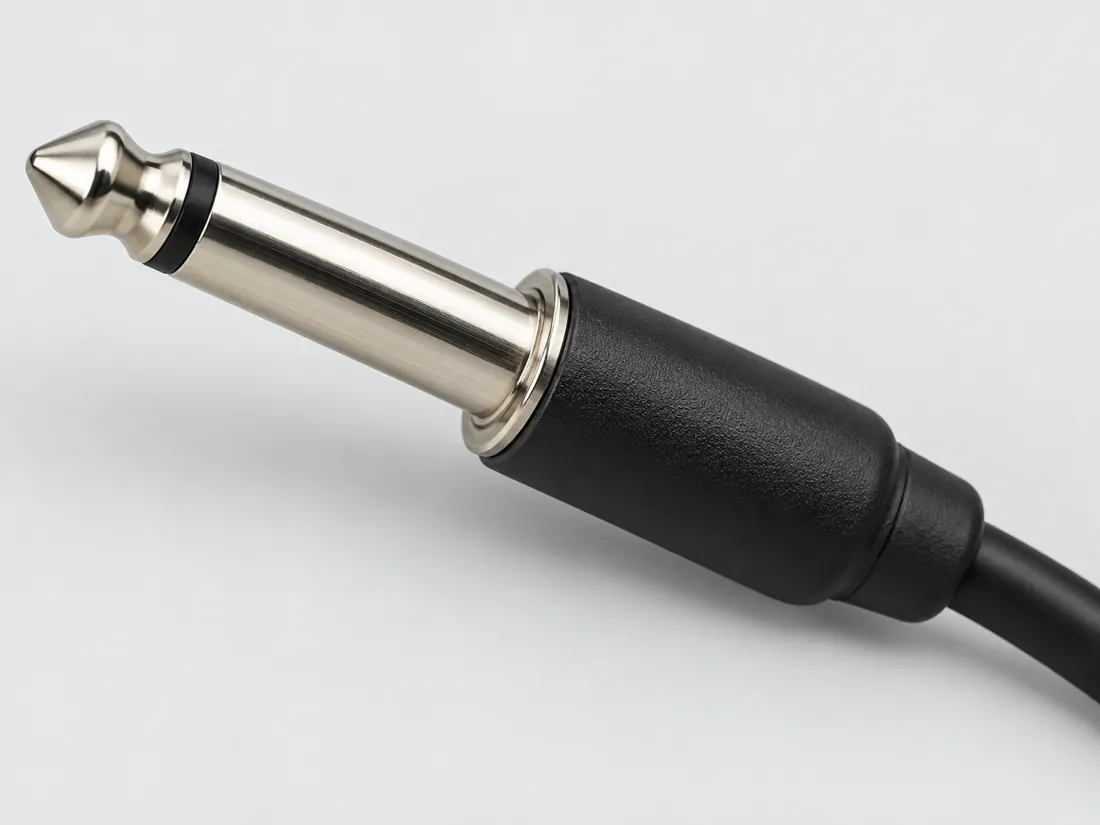
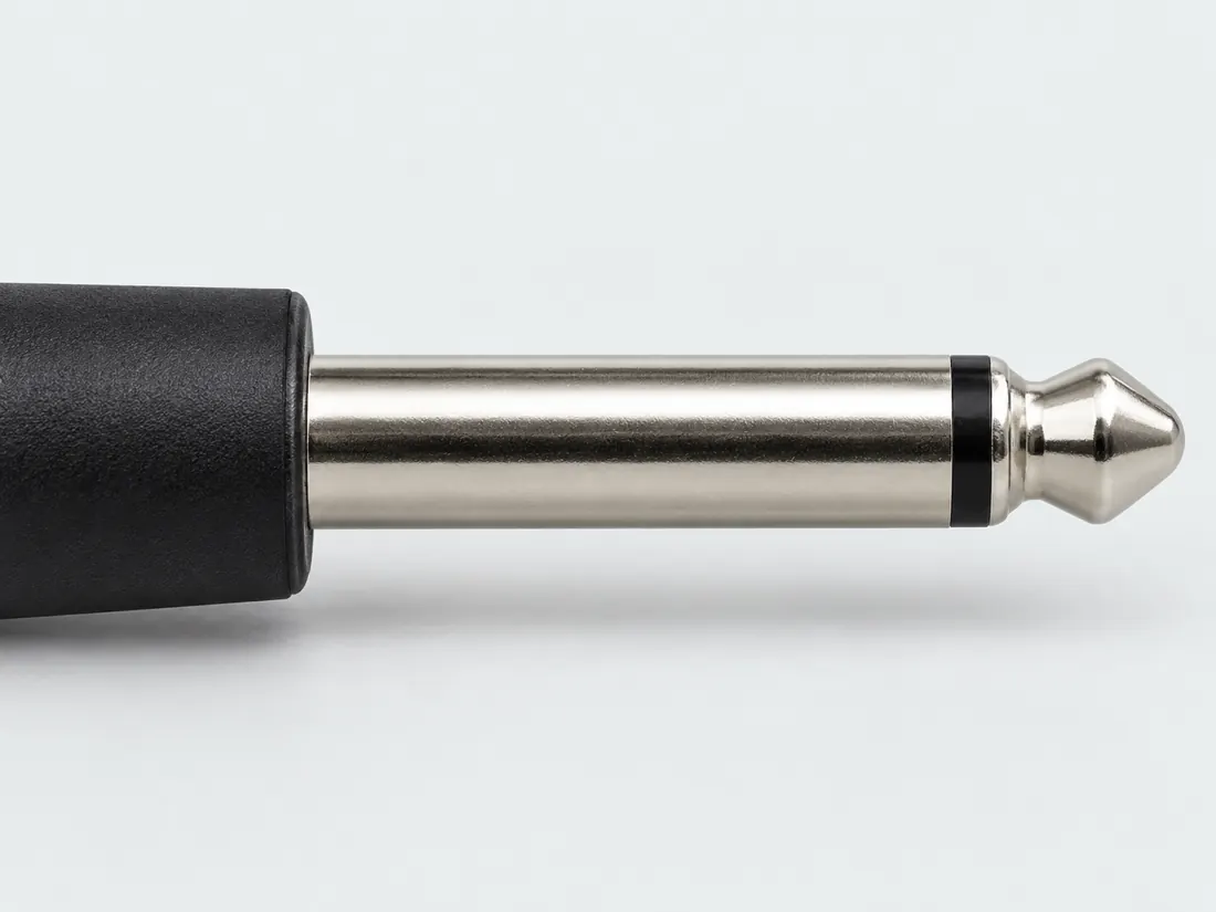
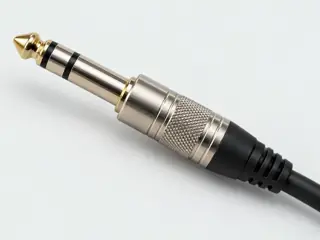
The 6.35 mm TS phone plug has two conductive sections.

Also called quarter inch TS 6.35mm mono 1/4 TS

A quarter-inch plug is a size, not a complete audio specification.

Look for

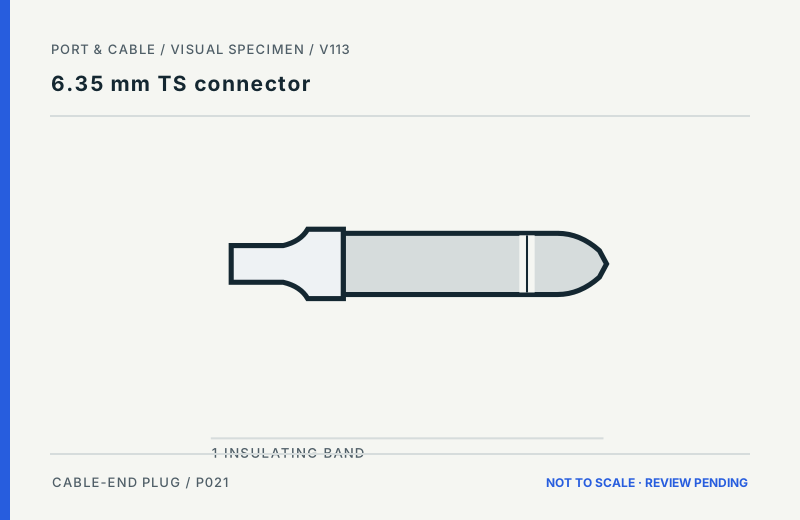
Distinguish its single insulating band from the two-band TRS version. Check the equipment labeling before connecting an instrument, output or input.

Claim inspection dates: 2026-10-01, 2026-10-11 · Independent review pending

Pins & wiring

Pinout

Choose the exact wiring. Pin numbers follow its stated view; a schematic does not establish physical positions. Check your exact device before wiring.

What the status labels mean
Confirmed
Recorded research passes agree within this variant; this is not independent human review or hardware validation.
Single source
Only one underlying document, or one pass, supports this assignment.
Device-specific
Supported for the named equipment or wiring only. Check your device’s manual.
Unverified
Missing or conflicting evidence. Do not wire from this row.
Not connected
The source explicitly says NC, no contact or no pin for this wiring.
Wiring variant

Yamaha EMX2 LINE 5/6-9/10 and MIC/LINE 4 (Hi-Z on) unbalanced inputs

Device-specific wiring. Check your device’s manual before connecting or applying power.

View and evidence limits

Plug contacts named tip/sleeve; no spatial face view.

  • P021 6.35 mm TS — **Agree** (tip = signal/hot, sleeve = ground) — A: Yamaha EMX2, MG32 and PX. B: Yamaha MG10XU and Mackie 1202VLZ4. Speaker-output use (tip +, sleeve −) is from A only.
  • No IEC 60268-12 or other standard text for the TS phone connector was accessed; mapping is device-specific only.
  • No primary manufacturer document was retrieved in this pass for instrument, footswitch, CV/gate or other TS applications.
  • Normalling / switch contacts on TS jacks (e.g. Switchcraft or Neutrik jack datasheets) were not established.
6.35 mm TS contact-designation referencePlug contacts named tip/sleeve; no spatial face view.SCHEMATIC · physical positions unconfirmedNot to scale · check the named wiring and device manualT: Signal (device_specific)TS: Ground (device_specific)SpowergrounddataConfigshieldNCUnknown
Schematic only · physical contact positions unconfirmed. Original drawing · not to scale. Scroll sideways if needed.
Yamaha EMX2 LINE 5/6-9/10 and MIC/LINE 4 (Hi-Z on) unbalanced inputs — source-scoped contact map
PinSignalWhat it doesStatus
TSignalControl, detection or configuration connection; check the source and device.Device-specific
Sources
SGroundGround reference and return.Device-specific
Sources
Sources (1)

Yamaha EMX2 SPEAKERS L/R phone outputs

Device-specific wiring. Check your device’s manual before connecting or applying power.

View and evidence limits

Plug contacts named tip/sleeve.

  • P021 6.35 mm TS — **Agree** (tip = signal/hot, sleeve = ground) — A: Yamaha EMX2, MG32 and PX. B: Yamaha MG10XU and Mackie 1202VLZ4. Speaker-output use (tip +, sleeve −) is from A only.
  • Loudspeaker-level output; table lists it as unbalanced with Tip: Positive, Sleeve: Negative.
  • No IEC 60268-12 or other standard text for the TS phone connector was accessed; mapping is device-specific only.
  • No primary manufacturer document was retrieved in this pass for instrument, footswitch, CV/gate or other TS applications.
  • Normalling / switch contacts on TS jacks (e.g. Switchcraft or Neutrik jack datasheets) were not established.
6.35 mm TS contact-designation referencePlug contacts named tip/sleeve.SCHEMATIC · physical positions unconfirmedNot to scale · check the named wiring and device manualT: Positive (device_specific)TS: Negative (device_specific)SpowergrounddataConfigshieldNCUnknown
Schematic only · physical contact positions unconfirmed. Original drawing · not to scale. Scroll sideways if needed.
Yamaha EMX2 SPEAKERS L/R phone outputs — source-scoped contact map
PinSignalWhat it doesStatus
TPositiveControl, detection or configuration connection; check the source and device.Device-specific
Sources
SNegativeControl, detection or configuration connection; check the source and device.Device-specific
Sources
Sources (1)

Yamaha MG32/14FX, MG24/14FX stereo channel input jacks and RETURN 1, 2

Device-specific wiring. Check your device’s manual before connecting or applying power.

View and evidence limits

Plug contacts named tip/sleeve.

  • P021 6.35 mm TS — **Agree** (tip = signal/hot, sleeve = ground) — A: Yamaha EMX2, MG32 and PX. B: Yamaha MG10XU and Mackie 1202VLZ4. Speaker-output use (tip +, sleeve −) is from A only.
  • No IEC 60268-12 or other standard text for the TS phone connector was accessed; mapping is device-specific only.
  • No primary manufacturer document was retrieved in this pass for instrument, footswitch, CV/gate or other TS applications.
  • Normalling / switch contacts on TS jacks (e.g. Switchcraft or Neutrik jack datasheets) were not established.
6.35 mm TS contact-designation referencePlug contacts named tip/sleeve.SCHEMATIC · physical positions unconfirmedNot to scale · check the named wiring and device manualT: Hot (device_specific)TS: Ground (device_specific)SpowergrounddataConfigshieldNCUnknown
Schematic only · physical contact positions unconfirmed. Original drawing · not to scale. Scroll sideways if needed.
Yamaha MG32/14FX, MG24/14FX stereo channel input jacks and RETURN 1, 2 — source-scoped contact map
PinSignalWhat it doesStatus
THotControl, detection or configuration connection; check the source and device.Device-specific
Sources
SGroundGround reference and return.Device-specific
Sources
Sources (1)

Yamaha PX10/PX8/PX5/PX3 [SPEAKERS] A/B phone output (BTL amplifier)

Device-specific wiring. Check your device’s manual before connecting or applying power.

View and evidence limits

Panel legend names tip/sleeve; no face view.

  • P021 6.35 mm TS — **Agree** (tip = signal/hot, sleeve = ground) — A: Yamaha EMX2, MG32 and PX. B: Yamaha MG10XU and Mackie 1202VLZ4. Speaker-output use (tip +, sleeve −) is from A only.
  • The PX uses BTL output stages: the sleeve is the inverted (NEG) output, not ground. The panel warns 'DO NOT CONNECT ANY OUTPUT TO GROUND'. Reference Manual p. 9 NOTICE also describes the BTL design.
  • No IEC 60268-12 or other standard text for the TS phone connector was accessed; mapping is device-specific only.
  • No primary manufacturer document was retrieved in this pass for instrument, footswitch, CV/gate or other TS applications.
  • Normalling / switch contacts on TS jacks (e.g. Switchcraft or Neutrik jack datasheets) were not established.
6.35 mm TS contact-designation referencePanel legend names tip/sleeve; no face view.SCHEMATIC · physical positions unconfirmedNot to scale · check the named wiring and device manualT: POS (device_specific)TS: NEG (inverted output) (device_specific)SpowergrounddataConfigshieldNCUnknown
Schematic only · physical contact positions unconfirmed. Original drawing · not to scale. Scroll sideways if needed.
Yamaha PX10/PX8/PX5/PX3 [SPEAKERS] A/B phone output (BTL amplifier) — source-scoped contact map
PinSignalWhat it doesStatus
TPOSControl, detection or configuration connection; check the source and device.Device-specific
Sources
SNEG (inverted output)Control, detection or configuration connection; check the source and device.Device-specific
Sources
Sources (1)

Yamaha MG10XU/MG10X/MG10 unbalanced LINE inputs (phone jack)

Device-specific wiring. Check your device’s manual before connecting or applying power.

View and evidence limits

Contacts identified by name; local ordinals 1 = tip, 2 = sleeve. No jack lug or PCB pad numbering is implied.

  • P021 6.35 mm TS — **Agree** (tip = signal/hot, sleeve = ground) — A: Yamaha EMX2, MG32 and PX. B: Yamaha MG10XU and Mackie 1202VLZ4. Speaker-output use (tip +, sleeve −) is from A only.
  • Loudspeaker-level TS outputs (e.g. Yamaha PX series 'Phones output jack' speaker terminals listed in YAM-PX10 p. 2), instrument outputs, footswitch/expression contacts and insert-tip-only wiring were not established pin by pin from a primary document in this pass.
  • Normalling/switch lugs on TS jacks are manufacturer-part-specific; no Switchcraft/Neutrik/Rean jack drawing was read in this pass.
6.35 mm TS contact-designation referenceContacts identified by name; local ordinals 1 = tip, 2 = sleeve. No jack lug or PCB pad numbering is implied.SCHEMATIC · physical positions unconfirmedNot to scale · check the named wiring and device manual1: Tip = Signal (device_specific)12: Sleeve = Ground (device_specific)2powergrounddataConfigshieldNCUnknown
Schematic only · physical contact positions unconfirmed. Original drawing · not to scale. Scroll sideways if needed.
Yamaha MG10XU/MG10X/MG10 unbalanced LINE inputs (phone jack) — source-scoped contact map
PinSignalWhat it doesStatus
1Tip = SignalControl, detection or configuration connection; check the source and device.Device-specific
Sources
2Sleeve = GroundControl, detection or configuration connection; check the source and device.Device-specific
Sources
Sources (1)

Mackie 1202VLZ4 line inputs, unbalanced TS plug wiring

Device-specific wiring. Check your device’s manual before connecting or applying power.

View and evidence limits

Contacts identified by name; local ordinals 1 = tip, 2 = sleeve. No jack lug or PCB pad numbering is implied.

  • P021 6.35 mm TS — **Agree** (tip = signal/hot, sleeve = ground) — A: Yamaha EMX2, MG32 and PX. B: Yamaha MG10XU and Mackie 1202VLZ4. Speaker-output use (tip +, sleeve −) is from A only.
  • Loudspeaker-level TS outputs (e.g. Yamaha PX series 'Phones output jack' speaker terminals listed in YAM-PX10 p. 2), instrument outputs, footswitch/expression contacts and insert-tip-only wiring were not established pin by pin from a primary document in this pass.
  • Normalling/switch lugs on TS jacks are manufacturer-part-specific; no Switchcraft/Neutrik/Rean jack drawing was read in this pass.
6.35 mm TS contact-designation referenceContacts identified by name; local ordinals 1 = tip, 2 = sleeve. No jack lug or PCB pad numbering is implied.SCHEMATIC · physical positions unconfirmedNot to scale · check the named wiring and device manual1: Tip = Positive (+ or hot) (device_specific)12: Sleeve = Shield or ground (device_specific)2powergrounddataConfigshieldNCUnknown
Schematic only · physical contact positions unconfirmed. Original drawing · not to scale. Scroll sideways if needed.
Mackie 1202VLZ4 line inputs, unbalanced TS plug wiring — source-scoped contact map
PinSignalWhat it doesStatus
1Tip = Positive (+ or hot)Control, detection or configuration connection; check the source and device.Device-specific
Sources
2Sleeve = Shield or groundCable screen or shield connection; check the named equipment.Device-specific
Sources
Sources (1)

Image inspection / P021

See the view. Check its scope.

2 registered views for this reference. Different part examples are not automatically mates; all remain not to scale and independently unapproved.

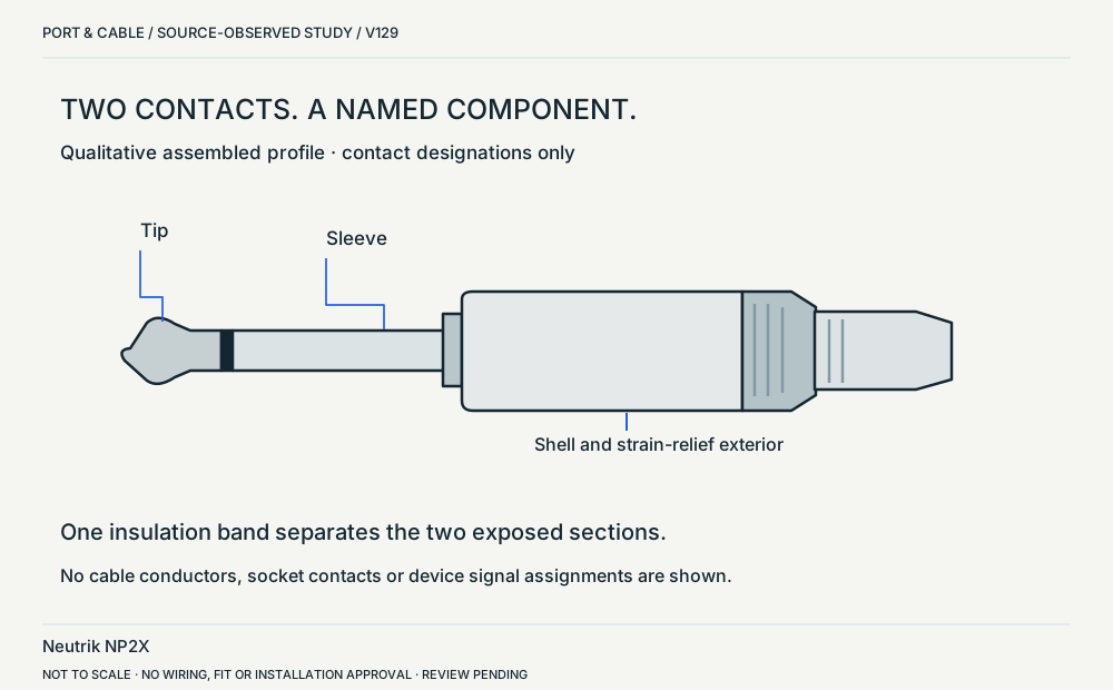
NP2X / two-pole profile. Side elevation in ST-NP2X. Exact part, qualitative side view. The nominal quarter-inch label is not copied as an exact measured diameter. (private workspace)

P021 / Source-observed physical study

NP2X / two-pole profile

Neutrik NP2X

Side elevation in ST-NP2X · Cable plug / cable end

Not to scale. Technical and rights review pending.

Inspect view & provenance (private workspace)
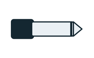
6.35 mm TS connector: Single insulating band / two metal sections. Side exterior of cable plug; qualitative band placement. Qualitative source-linked recognition study, not a pinout or a dimensional guide. (private workspace)

P021 / Inherited recognition study

6.35 mm TS connector

6.35 mm TS connector

Side exterior of cable plug; qualitative band placement · Cable plug / cable end

Not to scale. Technical and rights review pending.

Inspect view & provenance (private workspace)

Visual atlas / P021 / 2026

Recognize the right physical clue.

FIGURE · REVIEW PENDING
6.35 mm TS connector: Single insulating band / two metal sections. Side exterior of cable plug; qualitative band placement. Qualitative source-linked recognition study, not a pinout or a dimensional guide.
Cable-end plug. Side exterior of cable plug; qualitative band placement.

What to look for

Single insulating band / two metal sections

What the drawing does not prove

Band counts are documented; no geometric scale or wiring assignment.

The instrument or balanced-audio role depends on the equipment, not just the plug.

No fabrication dimensions, conductor routing, guaranteed fit or device approval. For electrical, power and optical interfaces, follow the original equipment instructions.

Figure evidence, orientation & usage rights

Uses previously recorded V112 manufacturer claim/source inspections; October 2026 supplementary public-source spot checks are documented separately, not treated as a refreshed approval.

Original Port & Cable interpretive vector, no third-party photo, copied CAD, logo or vendor drawing. Third-party product photos, logos and source drawings are not redistributed. No independent technical or rights certification is claimed.

Original claim identifiers: C021A (private workspace). Legacy evidence dates and rights assessments remain as recorded.

The useful distinction

Recognize it. Then verify it.

The 6.35 mm TS phone plug has two conductive sections. [C021A]

Neutrik customer drawing ST-NP2X labels the NP2X plug shaft diameter as 6.29 mm. This is a named-part drawing value, not an exact diameter for all nominal 6.35 mm TS connectors. [C021B]

Neutrik assembly instruction BDA 142-0 labels the NP2X termination paths Tip and Shield. Those component labels do not specify the signal carried by a connected instrument or amplifier. [C021C]

Source-scoped identification facts

Each value retains its exact example, role and measurement axis. Facts from different parts must not be combined into an invented component.

Documented examples; not a mating drawing or compatibility approval
Nominal contacts2S024phone plug physical contact sequence; nominal engineering count, not automatically positions, population or a device wiring map. phone plug physical contact sequence
Dimensions / axis6.35 mm Nominal plug family diameter; 14.5 mm published shell width (NP2X)S024 · S024Named source examples retain separate role, part, view and axis limits; values are not a universal family specification. nominal_identifier; phone plug physical contact sequence NP2X. Documented role: plug. 15.88mm jackfield pitch is connector-to-connector packing,not contact pitch.4–7mm cable acceptance excluded from connector dimensions.
Connector roleplug; plug (NP2X)S024 · S024Named source examples retain separate role, part, view and axis limits; values are not a universal family specification. phone plug physical contact sequence NP2X. Documented role: plug. 15.88mm jackfield pitch is connector-to-connector packing,not contact pitch.4–7mm cable acceptance excluded from connector dimensions.
ManufacturerNeutrik (NP2X)S024Named source examples retain separate role, part, view and axis limits; values are not a universal family specification. NP2X. Documented role: plug. 15.88mm jackfield pitch is connector-to-connector packing,not contact pitch.4–7mm cable acceptance excluded from connector dimensions.
SeriesPlug X (NP2X)S024Named source examples retain separate role, part, view and axis limits; values are not a universal family specification. NP2X. Documented role: plug. 15.88mm jackfield pitch is connector-to-connector packing,not contact pitch.4–7mm cable acceptance excluded from connector dimensions.
Exact part / implementationNP2X (NP2X)S024Named source examples retain separate role, part, view and axis limits; values are not a universal family specification. NP2X. Documented role: plug. 15.88mm jackfield pitch is connector-to-connector packing,not contact pitch.4–7mm cable acceptance excluded from connector dimensions.
View conventionLongitudinal plug view from the exposed tip toward the cable body: Tip → Sleeve.S024Recorded source-scoped values; named examples do not describe every family variant or establish compatibility. Existing engineering orientation text; source/part/view remains controlling.

Not recorded: Positions / cavity span, Populated contacts, Contact rows, Contact pitch, Contact gender / arrangement, Mounting, Coupling / latch, Keying / polarization, Shell / form, Recorded markings. Unknown fields stay unknown; illustrations supply no measurements or pin assignments.

Recorded variant and source limits
  • No instrument, speaker, insert or balanced/unbalanced device role is inferred.
  • No manufacturing tolerances are published.
  • Yamaha EMX2 LINE 5/6-9/10 and MIC/LINE 4 (Hi-Z on) unbalanced inputs: Plug contacts named tip/sleeve; no spatial face view.
  • Yamaha EMX2 SPEAKERS L/R phone outputs: Plug contacts named tip/sleeve.
  • Yamaha MG32/14FX, MG24/14FX stereo channel input jacks and RETURN 1, 2: Plug contacts named tip/sleeve.
  • Yamaha PX10/PX8/PX5/PX3 [SPEAKERS] A/B phone output (BTL amplifier): Panel legend names tip/sleeve; no face view.
  • Yamaha MG10XU/MG10X/MG10 unbalanced LINE inputs (phone jack): Contacts identified by name; local ordinals 1 = tip, 2 = sleeve. No jack lug or PCB pad numbering is implied.
  • Mackie 1202VLZ4 line inputs, unbalanced TS plug wiring: Contacts identified by name; local ordinals 1 = tip, 2 = sleeve. No jack lug or PCB pad numbering is implied.
Report a correction to these facts →

Bounded facts, visible unknowns

Specifications and limits

6.35 mm TS connector facts and limitations
Nominal diameter6.35 mm / 1/4 inch [C021A]
Conductive sections2: tip / sleeve [C021A]
Mechanical dimensionsNo independently reviewed mechanical drawing in this release; do not use this page for fabrication.
Engineering pinoutSource-checked engineering profile available; independent review pending. Open engineering profile →
Verified device listNot included. Check exact device and accessory documentation.
A boundary, not an omission to guess around.

This record is an identification starting point. It does not provide measured mating tolerances, electrical approval, or a list of verified device models. Use the original device and accessory documentation to resolve the remaining requirements.

Before you connect

What to check

  1. Identify the electrical role and signal level in the manual.
  2. Do not equate a physical size adapter with signal conversion.
  3. Confirm the intended wiring and destination.
Trace a supported connection class →

Your next step

Move from the form to the requirement.

The source trail

Evidence for this page

AI-assisted inspection is not independent engineering review. Source scope and access limitations are disclosed below. Procedural checklists are editorial requirements, not hardware measurements.

Back to first citation ↑
C021ASource checked · pending review

The 6.35 mm TS phone plug has two conductive sections.

Neutrik · NP2X phone plug ↗

Locator: Technical information
Access: public page.

S024: full source recordInspect review dependencies → (private workspace)

Claim scope: Consumer identification / documented standard or product class only. Next review due 2026-12-30.

Back to first citation ↑
C021BSource checked · pending review

Neutrik customer drawing ST-NP2X labels the NP2X plug shaft diameter as 6.29 mm. This is a named-part drawing value, not an exact diameter for all nominal 6.35 mm TS connectors.

Neutrik · Neutrik NP2X customer drawing ST-NP2X ↗

Locator: Sheet 1 of 1; main elevation, diameter callout and title block dated 04-Nov-2003.
Access: public pdf text. Named NP2X drawing labels the shaft diameter 6.29 mm. Not a universal 6.35 mm family dimension or a tolerance table. Raw source files are not bundled; linked observation and locator retained.

S524: full source recordInspect review dependencies → (private workspace)

Claim scope: Drawing ST-NP2X, sheet 1, 04-Nov-2003; tolerance stack, fit and other parts remain outside scope.. Next review due 2027-01-09.

Back to first citation ↑
C021CSource checked · pending review

Neutrik assembly instruction BDA 142-0 labels the NP2X termination paths Tip and Shield. Those component labels do not specify the signal carried by a connected instrument or amplifier.

Neutrik · Neutrik NP*X assembly instruction BDA 142-0 ↗

Locator: Single page; panel C terminal labels for NP2X and NP3X. Footer update 06-Nov-2010.
Access: public pdf text. Terminal names only. Not an equipment signal assignment, cable construction tutorial or approved assembly. Raw source files are not bundled; linked observation and locator retained.

S526: full source recordInspect review dependencies → (private workspace)

Claim scope: NP2X panel C terminal identification, not a universal audio signal or safety assignment.. Next review due 2027-01-09.

Suggest a correction to this field note →

Audio connection desk

Follow the signal beyond the plug

Signal roles, channel layouts and power requirements are distinct from connector shape. No hardware approval is implied.

Put this field note to work.

Add to discovery trayRecord an unsaved candidate (private workspace)

Candidate selection does not confirm the identity or capabilities of your physical item.

SOURCE-QUALIFIED AUDIO REFERENCE

Separate contact count from equipment role.

Neutrik NP2X

Role
Male cable plug; straight cable exit
Contacts
Two conducting sections; panel C names Tip and Shield termination paths.
Meaning
Nominal quarter-inch family. The named drawing labels a 6.29 mm shaft, not an exact 6.35 mm diameter.
Not established
Signal level, instrument/speaker suitability, mating tolerance and terminal wiring are not established.
Next check
Distinguish the family name from the exact part drawing; check the equipment input or output role.
Inspect the declared view → (private workspace)
Evidence, observation & limits

Inspected . C021B · C021C

Neutrik NP2X customer drawing ST-NP2X ↗
Sheet 1 of 1; main elevation, diameter callout and title block dated 04-Nov-2003.
Canonical source record S524 dated 2026-10-11. The V129 visit is recorded separately; inherited source dates are unchanged.

Neutrik NP*X assembly instruction BDA 142-0 ↗
Single page; panel C terminal labels for NP2X and NP3X. Footer update 06-Nov-2010.
Canonical source record S526 dated 2026-10-11. The V129 visit is recorded separately; inherited source dates are unchanged.

No hardware test, independent technical approval or rights clearance is asserted.

Read the illustrated audio chart and field guide →

Evidence behind this page

Scope first. Source second. Approval separate.

3 linked sources · 3 scoped claims · 0 sources with inspection/access flags.

Page scope: consumer_pilot

Assessment 2026-10-22 · earliest scheduled source review 2026-12-30. This is a recorded-date assessment, not a live source check. Page-level independent review is not established by this panel.

Inspect 3 source scopes, access limits and dates

S024 · NP2X phone plug

Neutrik · Manufacturer / product-owner domain · inspected 2026-10-01 · due 2026-12-30

Within inspection window

Scoped support: 1/4-inch 2-pole plug physical example.

Not established / limitations:

Locator: Technical information

S524 · Neutrik NP2X customer drawing ST-NP2X

Neutrik · Manufacturer / product-owner domain · inspected 2026-10-11 · due 2027-01-09

Within inspection window

Scoped support: Named NP2X drawing labels the shaft diameter 6.29 mm. Not a universal 6.35 mm family dimension or a tolerance table.

Not established / limitations: Named NP2X drawing labels the shaft diameter 6.29 mm. Not a universal 6.35 mm family dimension or a tolerance table. Raw source files are not bundled; linked observation and locator retained.

Locator: Sheet 1 of 1; main elevation, diameter callout and title block dated 04-Nov-2003.

S526 · Neutrik NP*X assembly instruction BDA 142-0

Neutrik · Manufacturer / product-owner domain · inspected 2026-10-11 · due 2027-01-09

Within inspection window

Scoped support: Terminal names only. Not an equipment signal assignment, cable construction tutorial or approved assembly.

Not established / limitations: Terminal names only. Not an equipment signal assignment, cable construction tutorial or approved assembly. Raw source files are not bundled; linked observation and locator retained.

Locator: Single page; panel C terminal labels for NP2X and NP3X. Footer update 06-Nov-2010.

Trace 3 claims to their source records

C021A · P021

The 6.35 mm TS phone plug has two conductive sections.

Claim scope: Consumer identification / documented standard or product class only

Source links: S024 · Evidence trail → (private workspace)

C021B · P021

Neutrik customer drawing ST-NP2X labels the NP2X plug shaft diameter as 6.29 mm. This is a named-part drawing value, not an exact diameter for all nominal 6.35 mm TS connectors.

Claim scope: Drawing ST-NP2X, sheet 1, 04-Nov-2003; tolerance stack, fit and other parts remain outside scope.

Source links: S524 · Evidence trail → (private workspace)

C021C · P021

Neutrik assembly instruction BDA 142-0 labels the NP2X termination paths Tip and Shield. Those component labels do not specify the signal carried by a connected instrument or amplifier.

Claim scope: NP2X panel C terminal identification, not a universal audio signal or safety assignment.

Source links: S526 · Evidence trail → (private workspace)

Prepare this page for review → (private workspace)Read the evidence method →

Recorded evidence only. An inspection date, publisher label, source link or generated packet is not independent technical review, hardware testing, fabrication approval or a compatibility verdict.