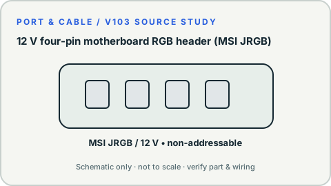
MSI documents its JRGB header as a four-pin 12 V connector for non-addressable RGB LED equipment, distinct from the five-volt addressable JRAINBOW family.
Also calledJRGB 12VRGB 4-pin motherboard header12V RGB headernonaddressable RGB header
Connecting a five-volt addressable LED accessory to a twelve-volt RGB header can damage the accessory.
Look for
Find the JRGB label and corresponding 12 V reference in the actual motherboard manual; do not decide by a loose RGB plug alone.
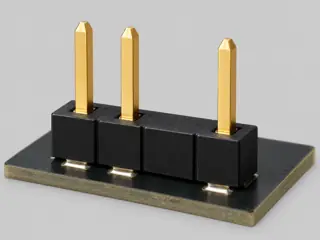
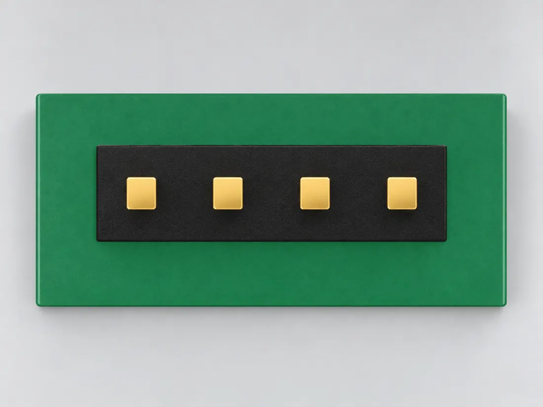
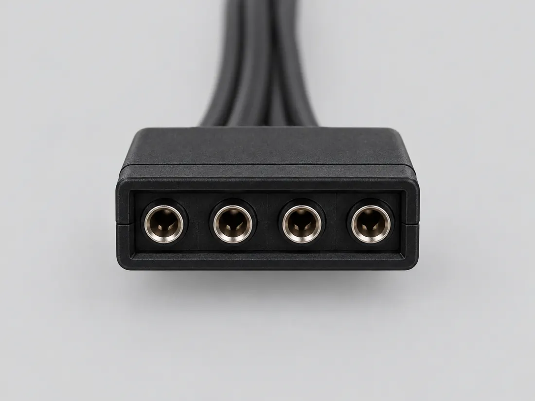
Three-quarter view Computer-generated illustration with prior AI visual review. Not a photograph, measurement or compatibility check. Independent technical and rights review pending.
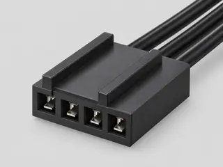
Mating face Computer-generated illustration with prior AI visual review. Not a photograph, measurement or compatibility check. Independent technical and rights review pending.
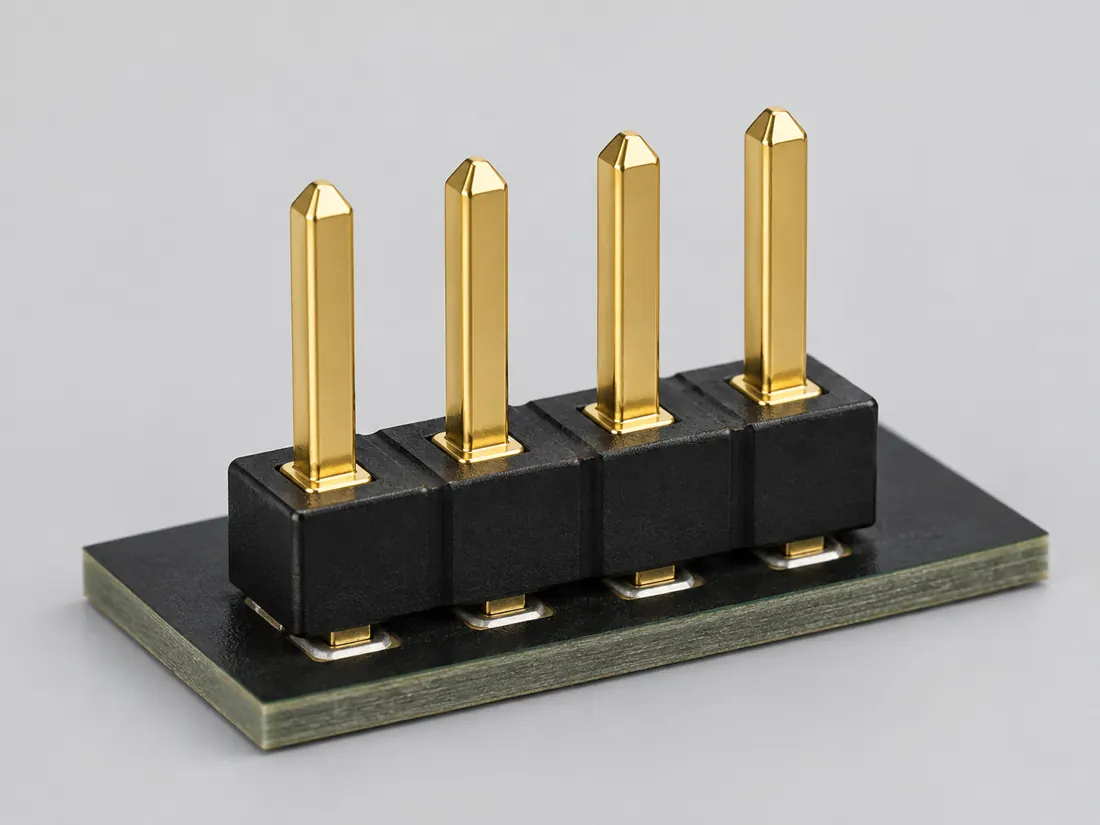
Fitted in place Computer-generated illustration with prior AI visual review. Not a photograph, measurement or compatibility check. Independent technical and rights review pending.
Recognition drawing Original schematic, not to scale. Drawing review pending.
Image inspection / P347
See the view. Check its scope.
1 registered view for this reference. Different part examples are not automatically mates; all remain not to scale and independently unapproved.
(private workspace)
P347 / Source-observed physical study
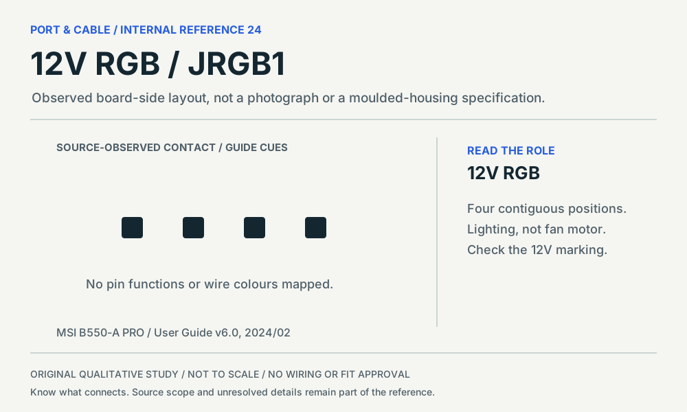
12V RGB / JRGB1
MSI B550-A PRO JRGB1
Board-side plan layout, following the cited diagram orientation · Board header
Not to scale. Technical and rights review pending.
Inspect view & provenance ↗ (private workspace)
INTERNAL SYSTEMS / HEADERS
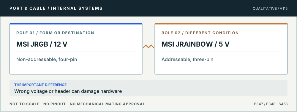
12 V four-pin RGB and 5 V addressable RGB are not interchangeable
No. MSI explicitly distinguishes its 12 V four-pin JRGB and 5 V three-pin JRAINBOW headers and warns incorrect connection may damage components. A shared “RGB” label does not resolve supply voltage or addressing method, and the warning must remain visible before any hookup.
Lighting: check the voltage first. Original qualitative role diagram; not mechanical artwork, not to scale or a wiring map. Source context S458.
Three checks before proceeding
Disconnect power and read the exact motherboard/strip manuals.
Confirm voltage, addressable mode, pin/arrow orientation and any controller.
Never force or electrically bridge a 12 V header to a 5 V addressable load.
One mistake to avoid
Using an improvised adapter to power a 5 V strip from an unverified 12 V header.
Claim-specific evidence remains in the canonical record. Concept diagrams do not show any safe wiring or mechanical mating geometry.
The useful distinction
Recognize it. Then verify it.
MSI documents its JRGB header as a four-pin 12 V connector for non-addressable RGB LED equipment, distinct from the five-volt addressable JRAINBOW family. [C347A]
MSI warns that connecting a five-volt LED strip to its twelve-volt JRGB header causes damage. [C347B]
B550-A PRO describes JRGB1 as a four-position 12V 5050 RGB-strip connection. [C347C]
MSI’s RGB-fan diagram separates the lighting lead from the system-fan connection. [C347D]
MSI warns that connecting a 5V LED strip to JRGB can damage the strip. [C347E]
PC internals · a documented check
Can a 5V ARGB lead go on a 12V RGB header?
Not on the MSI headers described here. JRGB is a 12V four-pin lighting connection; JRAINBOW is a 5V three-pin addressable connection. MSI warns that connecting a 5V strip to JRGB damages the strip. C347A · C348A · C347B
What the documentation establishes—and what still needs checking
Documented distinction5V, three-pin addressable interface; the B550-A PRO drawing has a gap at position 3. C348A · C348D
BoundaryDo not generalize its gap or voltage to another maker’s three-pin connector.
Fan assembly
Documented distinctionThe B550-A PRO RGB-fan illustration separates lighting and system-fan connections. C347D
BoundaryThe fan-motor lead and lighting lead are different paths.
Check these next
Read the board and lighting-device manuals for voltage, header name and controller requirements.
Distinguish the motor/control lead from the lighting lead on a combined fan assembly.
Follow the maker’s power-off and disconnection instructions before changes; stop at a voltage mismatch.
Keep this limit: Do not connect a 5V strip to JRGB. No passive adapter, rewiring method or general cross-brand lighting approval is provided. C347B · C348B
Identify the documented form
Separate MSI JRGB lighting from addressable lighting and fan power.
The documented JRGB designation is the non-addressable lighting family, distinct from JRAINBOW. S458 · S458
MSI’s diagram separates the lighting lead from the system-fan connection. S591
Documented identity facts; exact part and variant scope remains with each value
Nominal contacts
4 (MSI JRGB)S458Recorded source-scoped values; named examples do not describe every family variant or establish compatibility. Manufacturer-specific family/physical identification only. No inferred device wiring, mating verification or installation approval.
Positions / cavity span
4 (Claim C347C); 4 (MSI B550-A PRO JRGB1)S591 · S757Separate exact examples; retain each value’s source, role, axis and part scope. V142: named MSI B550-A PRO manual version 6.0 (2024/02) or explicitly identified Noctua family only. Role/recognition evidence, not generic wiring, safe mating, pinout approval, dimensions or installed-device certification.
Populated contacts
4 (MSI JRGB); 4 (MSI B550-A PRO JRGB1)S458 · S757Separate exact examples; retain each value’s source, role, axis and part scope. Manufacturer-specific family/physical identification only. No inferred device wiring, mating verification or installation approval. Exact named example MSI B550-A PRO JRGB1: Device-specific12V RGB header. Exact example only; no universal geometry, electrical compatibility, fabrication approval or wiring instruction. No2.54mmpitch inferred. Reference designator in diagram is not evidence of physical specimen markings.
Connector role
header (MSI JRGB)S458Recorded source-scoped values; named examples do not describe every family variant or establish compatibility. Manufacturer-specific family/physical identification only. No inferred device wiring, mating verification or installation approval.
Rows, pitch, dimensions, keying and view limits
Additional scoped facts; not a fabrication drawing or a mating approval
Contact rows
1 (MSI B550-A PRO JRGB1)S757Separate exact examples; retain each value’s source, role, axis and part scope. Exact named example MSI B550-A PRO JRGB1: Device-specific12V RGB header. Exact example only; no universal geometry, electrical compatibility, fabrication approval or wiring instruction. No2.54mmpitch inferred. Reference designator in diagram is not evidence of physical specimen markings.
Contact pitch
Not recordedNot recorded in a normalized source-scoped field. Consult the exact part/revision; no value inferred from illustrations.
Dimensions / axis
Not recordedNot recorded in a normalized source-scoped field. Consult the exact part/revision; no value inferred from illustrations.
Coupling / latch
Not recordedNot recorded in a normalized source-scoped field. Consult the exact part/revision; no value inferred from illustrations.
Keying / polarization
Not recordedNot recorded in a normalized source-scoped field. Consult the exact part/revision; no value inferred from illustrations.
View convention
MSI p.40 numbered header sketch, pin1left; single row of4. Cable rear orientation is outside this sketch. (MSI B550-A PRO JRGB1)S757Separate exact examples; retain each value’s source, role, axis and part scope. Exact named example MSI B550-A PRO JRGB1: Device-specific12V RGB header. Exact example only; no universal geometry, electrical compatibility, fabrication approval or wiring instruction. No2.54mmpitch inferred. Reference designator in diagram is not evidence of physical specimen markings.
Contact gender / arrangement
Not recordedNot recorded in a normalized source-scoped field. Consult the exact part/revision; no value inferred from illustrations.
Mounting
Not recordedNot recorded in a normalized source-scoped field. Consult the exact part/revision; no value inferred from illustrations.
Shell / form
Not recordedNot recorded in a normalized source-scoped field. Consult the exact part/revision; no value inferred from illustrations.
Manufacturer
MSI (B550-A PRO JRGB1)S591Recorded source-scoped values; named examples do not describe every family variant or establish compatibility. V142: named MSI B550-A PRO manual version 6.0 (2024/02) or explicitly identified Noctua family only. Role/recognition evidence, not generic wiring, safe mating, pinout approval, dimensions or installed-device certification.
Series
JRGB (B550-A PRO JRGB1)S591Recorded source-scoped values; named examples do not describe every family variant or establish compatibility. V142: named MSI B550-A PRO manual version 6.0 (2024/02) or explicitly identified Noctua family only. Role/recognition evidence, not generic wiring, safe mating, pinout approval, dimensions or installed-device certification.
Exact part / implementation
B550-A PRO JRGB1 (B550-A PRO JRGB1)S591Recorded source-scoped values; named examples do not describe every family variant or establish compatibility. V142: named MSI B550-A PRO manual version 6.0 (2024/02) or explicitly identified Noctua family only. Role/recognition evidence, not generic wiring, safe mating, pinout approval, dimensions or installed-device certification.
Recorded markings
Not recordedNot recorded in a normalized source-scoped field. Consult the exact part/revision; no value inferred from illustrations.
Keep this limit: MSI warns that the lower-voltage strip connected to the higher-voltage JRGB header can be damaged. S458 · S591
Make the next check
Read the exact board’s JRGB label, voltage and accessory compatibility; follow its power-off instructions.
12 V four-pin motherboard RGB header (MSI JRGB) facts and limitations
Documented MSI JRGB form
Four contacts; 12 V lighting category — not a universal wiring map [C347A]
Role and recognition scope
Board header — MSI B550-A PRO JRGB1. Original qualitative study only; no wiring or fit approval. [C347C][C347D][C347E]
Mechanical dimensions
Only manufacturer-described nominal family/footprint pitch is quoted in sourced text; no measured fabrication/tolerance drawing independently approved.
Not included. Check exact device and accessory documentation.
A boundary, not an omission to guess around.
Switch the PC off, remove mains power, and confirm the header labels before attaching lighting equipment. Check both the motherboard’s header voltage and the LED product’s required voltage and pin allocation. Never mate a 5 V ARGB plug to a 12 V RGB port, even with a mechanical adapter.
Before you connect
What to check
Switch the PC off, remove mains power, and confirm the header labels before attaching lighting equipment.
Check both the motherboard’s header voltage and the LED product’s required voltage and pin allocation.
Never mate a 5 V ARGB plug to a 12 V RGB port, even with a mechanical adapter.
Choose the exact wiring. Pin numbers follow its stated view; a schematic does not establish physical positions. Check your exact device before wiring.
What the status labels mean
Confirmed
Recorded research passes agree within this variant; this is not independent human review or hardware validation.
Single source
Only one underlying document, or one pass, supports this assignment.
Device-specific
Supported for the named equipment or wiring only. Check your device’s manual.
Unverified
Missing or conflicting evidence. Do not wire from this row.
Not connected
The source explicitly says NC, no contact or no pin for this wiring.
Important boundary
This reference establishes only the specific manufacturer-documented family and example noted in the sources. It does not verify an arbitrary mating pair, cable orientation, electrical rating or device combination. Stop and consult original documents for the exact products.
Source-scoped V142 recognition check
MSI B550-A PRO JRGB1. Four contiguous positions in the JRGB1 source diagram. Lighting control is distinct from fan-motor control. Identify the lighting supply and header label; do not substitute an ARGB strip. Still unresolved: Strip/controller compatibility, total lighting load and proprietary lighting systems. See the internal-header field reference for source revision, observation limits and the comparison.
AI-assisted inspection is not independent engineering review. Source scope and access limitations are disclosed below. Procedural checklists are editorial requirements, not hardware measurements.
Locator: JRGB connector; JRAINBOW connector; warning on voltage mismatch; motherboard manual check Access: public page. Other LED headers and proprietary variants exist. No universal header assignment or exact LED current assumption.
Claim scope: Manufacturer-specific family/physical identification only. No inferred device wiring, mating verification or installation approval.. Next review due 2027-01-07.
Locator: PDF pp.33, 36–38, 40–41; p.59 / printed ix revision history. Source diagrams visually inspected at zero-based pages 32,35,36,37,39,40,58. Access: public pdf text. Observed document is not a real-hardware inspection, installed-device approval, wiring guide, current revision guarantee or manufacturing specification.
Claim scope: V142: named MSI B550-A PRO manual version 6.0 (2024/02) or explicitly identified Noctua family only. Role/recognition evidence, not generic wiring, safe mating, pinout approval, dimensions or installed-device certification.. Next review due 2027-01-11.
Assessment 2026-10-22 · earliest scheduled source review 2027-01-07. This is a recorded-date assessment, not a live source check. Page-level independent review is not established by this panel.
Scoped support: Named B550-A PRO board header identities, diagram-level contact/key arrangements, control modes and RGB mismatch warnings.
Not established / limitations: Observed document is not a real-hardware inspection, installed-device approval, wiring guide, current revision guarantee or manufacturing specification.
Locator: PDF pp.33, 36–38, 40–41; p.59 / printed ix revision history. Source diagrams visually inspected at zero-based pages 32,35,36,37,39,40,58.
Trace 5 claims to their source records
C347A · P347
MSI identifies JRGB as a 12 V, four-pin motherboard lighting header.
Claim scope: Manufacturer-specific family/physical identification only. No inferred device wiring, mating verification or installation approval.
B550-A PRO describes JRGB1 as a four-position 12V 5050 RGB-strip connection.
Claim scope: V142: named MSI B550-A PRO manual version 6.0 (2024/02) or explicitly identified Noctua family only. Role/recognition evidence, not generic wiring, safe mating, pinout approval, dimensions or installed-device certification.
MSI’s RGB-fan diagram separates the lighting lead from the system-fan connection.
Claim scope: V142: named MSI B550-A PRO manual version 6.0 (2024/02) or explicitly identified Noctua family only. Role/recognition evidence, not generic wiring, safe mating, pinout approval, dimensions or installed-device certification.
MSI warns that connecting a 5V LED strip to JRGB can damage the strip.
Claim scope: V142: named MSI B550-A PRO manual version 6.0 (2024/02) or explicitly identified Noctua family only. Role/recognition evidence, not generic wiring, safe mating, pinout approval, dimensions or installed-device certification.
Recorded evidence only. An inspection date, publisher label, source link or generated packet is not independent technical review, hardware testing, fabrication approval or a compatibility verdict.

 (private workspace)