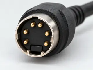
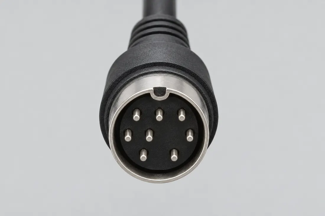
Three-quarter view Computer-generated illustration with prior AI visual review. Not a photograph, measurement or compatibility check. Independent technical and rights review pending.
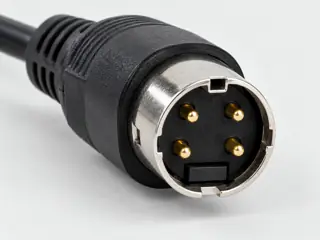
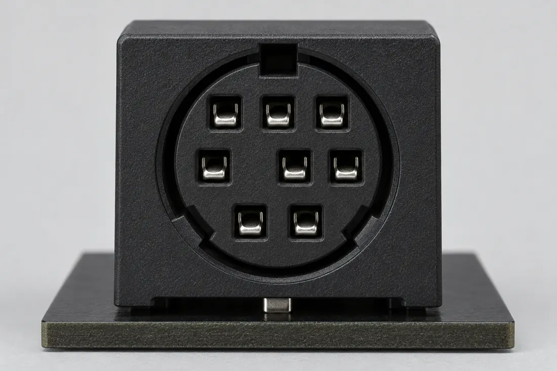
Mating face Computer-generated illustration with prior AI visual review. Not a photograph, measurement or compatibility check. Independent technical and rights review pending.
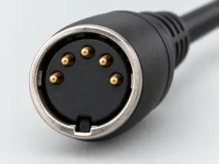
Fitted in place Computer-generated illustration with prior AI visual review. Not a photograph, measurement or compatibility check. Independent technical and rights review pending.
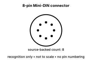
Recognition drawing Original schematic, not to scale. Drawing review pending.
Image inspection / P210
See the view. Check its scope.
1 registered view for this reference. Different part examples are not automatically mates; all remain not to scale and independently unapproved.
(private workspace)
P210 / Source-observed physical study
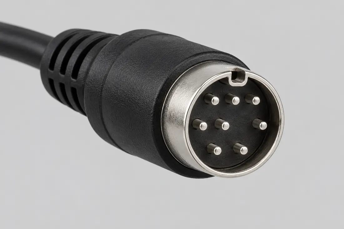
Eight-position Mini-DIN / MD-80S
CUI MD-S / dated 2022 manufacturer document
Named MD-80S front detail / upper key kept above · Device receptacle
Not to scale. Technical and rights review pending.
Inspect view & provenance ↗ (private workspace)
The useful distinction
Recognize it. Then verify it.
Eight-position Mini-DIN is a keyed circular connector form distinct from the four- and six-position Mini-DIN variants. [C210A]
The MD-S datasheet identifies option 80 as eight pins within its non-shielded, right-angle PCB component series. [C210B]
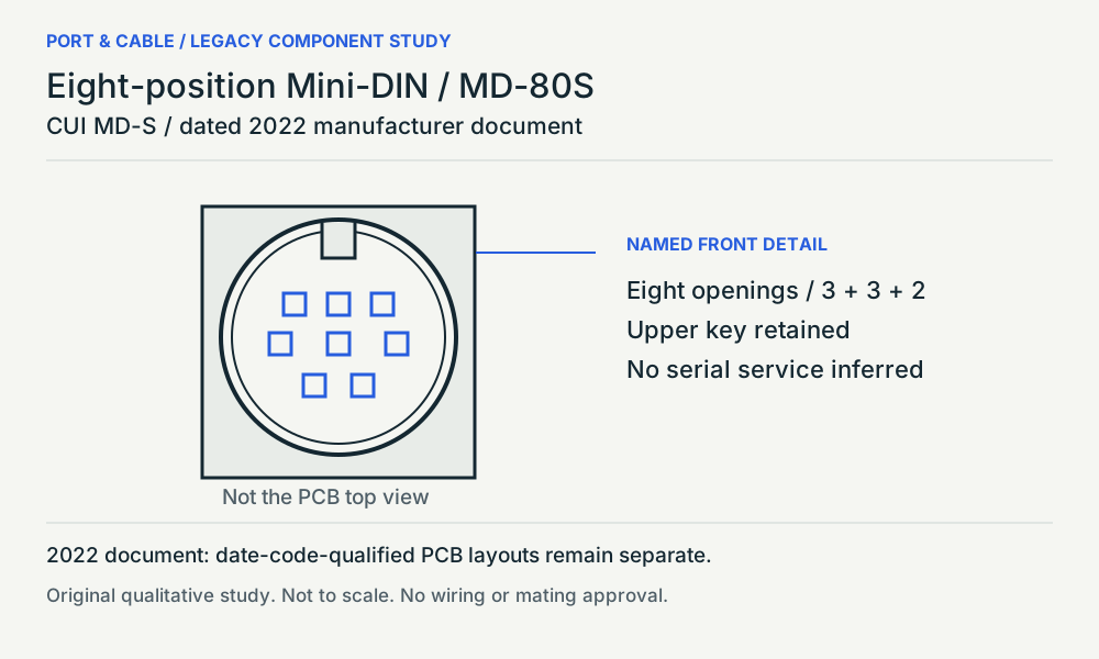
The named MD-80S front detail shows eight contact openings in groups of three, three and two; its PCB-layout views carry separate date-code qualifications. [C210C]
Source-scoped identification facts
Each value retains its exact example, role and measurement axis. Facts from different parts must not be combined into an invented component.
Documented examples; not a mating drawing or compatibility approval
Nominal contacts
8S213Source-backed position count only; V36 does not publish a wiring assignment.
Positions / cavity span
8 (Claim C210A)S213Recorded source-scoped values; named examples do not describe every family variant or establish compatibility. V36 catalogue-expansion identification fact only; not independent technical approval, fabrication data, wiring instruction or end-to-end compatibility proof.
Dimensions / axis
12.83 mm manufacturer-labelled connector height (5749268-1); 16.51 mm manufacturer-labelled product length (5749268-1); 14 mm manufacturer-labelled product width (5749268-1)S213Named source examples retain separate role, part, view and axis limits; values are not a universal family specification. 5749268-1. Documented role: socket. Catalog6.5mm centerline lacks contact-axis interpretation; withheld from normalized pitch.; 5749263-1 page swaps height/length relative to6/8position pages; values retained exactly labelled, not silently corrected. Drawing comparison remains needed.
Connector role
socket (5749268-1)S213Named source examples retain separate role, part, view and axis limits; values are not a universal family specification. 5749268-1. Documented role: socket. Catalog6.5mm centerline lacks contact-axis interpretation; withheld from normalized pitch.; 5749263-1 page swaps height/length relative to6/8position pages; values retained exactly labelled, not silently corrected. Drawing comparison remains needed.
Keying / polarization
Mating polarization; right-angle boardmount receptacle (5749268-1)S213Named source examples retain separate role, part, view and axis limits; values are not a universal family specification. 5749268-1. Documented role: socket. Catalog6.5mm centerline lacks contact-axis interpretation; withheld from normalized pitch.; 5749263-1 page swaps height/length relative to6/8position pages; values retained exactly labelled, not silently corrected. Drawing comparison remains needed.
Manufacturer
TE Connectivity (5749268-1)S213Named source examples retain separate role, part, view and axis limits; values are not a universal family specification. 5749268-1. Documented role: socket. Catalog6.5mm centerline lacks contact-axis interpretation; withheld from normalized pitch.; 5749263-1 page swaps height/length relative to6/8position pages; values retained exactly labelled, not silently corrected. Drawing comparison remains needed.
Series
Circular Mini DIN (5749268-1)S213Named source examples retain separate role, part, view and axis limits; values are not a universal family specification. 5749268-1. Documented role: socket. Catalog6.5mm centerline lacks contact-axis interpretation; withheld from normalized pitch.; 5749263-1 page swaps height/length relative to6/8position pages; values retained exactly labelled, not silently corrected. Drawing comparison remains needed.
Exact part / implementation
5749268-1 (5749268-1)S213Named source examples retain separate role, part, view and axis limits; values are not a universal family specification. 5749268-1. Documented role: socket. Catalog6.5mm centerline lacks contact-axis interpretation; withheld from normalized pitch.; 5749263-1 page swaps height/length relative to6/8position pages; values retained exactly labelled, not silently corrected. Drawing comparison remains needed.
Not recorded: Populated contacts, Contact rows, Contact pitch, Contact gender / arrangement, Mounting, Coupling / latch, Shell / form, Recorded markings, View convention. Unknown fields stay unknown; illustrations supply no measurements or pin assignments.
Recorded variant and source limits
Check the exact device manual before wiring or applying power.
Apple Macintosh Plus serial ports (modem/printer), Mini DIN-8: Apple Figure 1 labels the drawing '(Female Connector)': top row 8-7-6, middle 5-4-3, bottom 2-1 (as drawn).
Apple Macintosh SE, Macintosh II and Portable families (GPi-capable serial ports), DIN-8: Contact numbers only.
Apple Macintosh Plus serial ports (modem/printer): Mini-DIN-8 contact numbers. Apple HW10 Figure 1 labels the female connector face: 8 7 6 top row, 5 4 3 middle, 2 1 bottom (positions as drawn; no other view inferred).
Apple Macintosh models with GPi (SE, II and Portable families per DV16): Mini-DIN-8 contact numbers. Apple HW10 Figure 1 labels the female connector face: 8 7 6 top row, 5 4 3 middle, 2 1 bottom (positions as drawn; no other view inferred).
The MD-S datasheet identifies option 80 as eight pins within its non-shielded, right-angle PCB component series. [C210B]
Source-scoped component observation
The named MD-80S front detail shows eight contact openings in groups of three, three and two; its PCB-layout views carry separate date-code qualifications. [C210C]
Mechanical dimensions
No independently reviewed mechanical drawing in V36; do not use this page for fabrication, fit testing or tolerance work.
Not included. Check exact device and accessory documentation.
A boundary, not an omission to guess around.
Use the source-backed form or position count only for identification. Resolve ratings, protocol, direction, wiring, cable construction and exact device support from the relevant equipment and component documentation.
Before you connect
What to check
Identify the exact connector family and variant from the equipment or cable documentation.
Keep shape, contact count, protocol, electrical rating and device support as separate facts.
Do not force, rewire or adapt a connector from this recognition record; resolve the remaining requirements first.
Choose the exact wiring. Pin numbers follow its stated view; a schematic does not establish physical positions. Check your exact device before wiring.
What the status labels mean
Confirmed
Recorded research passes agree within this variant; this is not independent human review or hardware validation.
Single source
Only one underlying document, or one pass, supports this assignment.
Device-specific
Supported for the named equipment or wiring only. Check your device’s manual.
Unverified
Missing or conflicting evidence. Do not wire from this row.
Not connected
The source explicitly says NC, no contact or no pin for this wiring.
What is not established
This field note does not approve a connection, adapter, cable assembly, rewiring scheme or fabricated part. It intentionally omits unsupported pin assignments and mechanical tolerances.
V149 — Eight positions still need an equipment identity.
MD-80S supplies a dated eight-contact component example. Its front detail is not the board-footprint view. Contact count does not assign serial or A/V service, identify a compatible adapter or establish a current replacement part.
Source-facing view, not a connection approval
The original qualitative study is linked through the legacy component reference and Visual Atlas. No live testing, trial fitting, rewiring, measured geometry, universal pinout or independent approval is provided. Retain the exact source revision and equipment manual.
AI-assisted inspection is not independent engineering review. Source scope and access limitations are disclosed below. Procedural checklists are editorial requirements, not hardware measurements.
Locator: Product detail fields Access: public page. Identification/reference scope only. V36 does not convert this source into a universal pinout, fabrication drawing, electrical approval or end-to-end compatibility verdict.
Locator: Pages 1 and 3 of 5 visually inspected: pin-options key, named MD-60S and MD-80S front details and date-code-qualified PCB layouts. Date 02/18/2022; revision history lists 1.07. Access: public page. Historical manufacturer document, distributor-hosted. Non-shielded right-angle PCB component family; named six/eight contact patterns. Current manufacturer pages could not be retrieved; no current revision, availability, PS/2 or serial service is established. Raw source file possession and byte hash are not claimed; only the available web observations are recorded.
The named MD-80S front detail shows eight contact openings in groups of three, three and two; its PCB-layout views carry separate date-code qualifications.
Locator: Pages 1 and 3 of 5 visually inspected: pin-options key, named MD-60S and MD-80S front details and date-code-qualified PCB layouts. Date 02/18/2022; revision history lists 1.07. Access: public page. Historical manufacturer document, distributor-hosted. Non-shielded right-angle PCB component family; named six/eight contact patterns. Current manufacturer pages could not be retrieved; no current revision, availability, PS/2 or serial service is established. Raw source file possession and byte hash are not claimed; only the available web observations are recorded.
Claim scope: Source-facing component recognition only. The PCB top view is not reused as a mating face, and no universal signal map or replacement footprint is supplied.. Next review due 2027-01-11.
Candidate selection does not confirm the identity or capabilities of your physical item.
SOURCE-OBSERVED LEGACY COMPONENT
Eight positions still need an equipment identity.
MD-80S supplies a dated eight-contact component example. Its front detail is not the board-footprint view. Contact count does not assign serial or A/V service, identify a compatible adapter or establish a current replacement part.
CUI MD-S / dated 2022 manufacturer document Right-angle PCB socket / non-shielded series · Source, view and omissions (private workspace)Read the evidence and its limits
The MD-S datasheet identifies option 80 as eight pins within its non-shielded, right-angle PCB component series. C210B
MD-80S in the dated manufacturer document only; no current-production, serial-port or adapter claim.
The named MD-80S front detail shows eight contact openings in groups of three, three and two; its PCB-layout views carry separate date-code qualifications. C210C
Source-facing component recognition only. The PCB top view is not reused as a mating face, and no universal signal map or replacement footprint is supplied.
Assessment 2026-10-22 · earliest scheduled source review 2027-01-03. This is a recorded-date assessment, not a live source check. Page-level independent review is not established by this panel.
TE Connectivity · Manufacturer / product-owner domain · inspected 2026-10-05 · due 2027-01-03
Within inspection window
Scoped support: Identifies an eight-position circular Mini-DIN connector product and its keyed/polarized form.
Not established / limitations: Identification/reference scope only. V36 does not convert this source into a universal pinout, fabrication drawing, electrical approval or end-to-end compatibility verdict.
CUI Devices (manufacturer document hosted by RS) · Unclassified publisher domain · inspected 2026-10-13 · due 2027-01-11
Within inspection window
Scoped support: Historical manufacturer document, distributor-hosted. Non-shielded right-angle PCB component family; named six/eight contact patterns. Current manufacturer pages could not be retrieved; no current revision, availability, PS/2 or serial service is established.
Not established / limitations: Historical manufacturer document, distributor-hosted. Non-shielded right-angle PCB component family; named six/eight contact patterns. Current manufacturer pages could not be retrieved; no current revision, availability, PS/2 or serial service is established. Raw source file possession and byte hash are not claimed; only the available web observations are recorded.
Locator: Pages 1 and 3 of 5 visually inspected: pin-options key, named MD-60S and MD-80S front details and date-code-qualified PCB layouts. Date 02/18/2022; revision history lists 1.07.
Trace 3 claims to their source records
C210A · P210
TE identifies the cited product as an eight-position keyed/polarized circular Mini-DIN connector.
Claim scope: V36 catalogue-expansion identification fact only; not independent technical approval, fabrication data, wiring instruction or end-to-end compatibility proof.
The named MD-80S front detail shows eight contact openings in groups of three, three and two; its PCB-layout views carry separate date-code qualifications.
Claim scope: Source-facing component recognition only. The PCB top view is not reused as a mating face, and no universal signal map or replacement footprint is supplied.
Recorded evidence only. An inspection date, publisher label, source link or generated packet is not independent technical review, hardware testing, fabrication approval or a compatibility verdict.

 (private workspace)