
FIELD REFERENCE 32 / APPLIANCE POWER
Find the cord end.
Confirm the inlet.
C17 and C18 describe opposite sides of an appliance connection. Use these source-observed examples to identify the role, then keep the exact cord, inlet and equipment requirements together.
01 / A CONNECTOR IS NOT A WHOLE SYSTEM
Two contacts. Two different roles.
C17/C18 is a documented Class II, non-grounded pair. Do not identify it by imagining a removed earth contact, or use this reference to alter equipment requiring protective earth.
Read the evidence and its limits
Interpower identifies C17/C18 as a Class II pair for applications not requiring a ground path; V40 normalizes that as a two-pole, no-protective-earth boundary. C215B
V40 engineering-reference fact only; independent human review remains pending. This claim does not approve fabrication, rewiring, substitution, electrical safety, protocol support or end-to-end compatibility.
Interpower identifies C17/C18 as a Class II pair for applications not requiring a ground path; V40 normalizes that as a two-pole, no-protective-earth boundary. C216B
V40 engineering-reference fact only; independent human review remains pending. This claim does not approve fabrication, rewiring, substitution, electrical safety, protocol support or end-to-end compatibility.
IEC 60320 C17 cord connector
C17 is the cord end, not the complete power decision.
OBLIQUE PHOTOGRAPH STUDY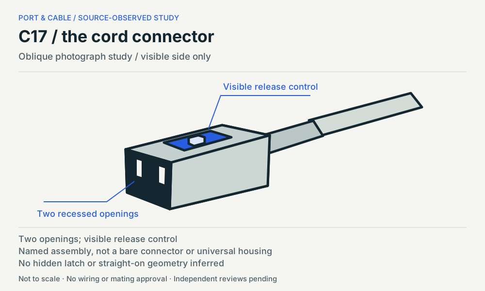
Cord end / molded V-Lock example · Source, view and omissions (private workspace)
The named 3-101-794 example is an assembled North American power cord. Its oblique-photo study shows the C17 end and visible release control, not a universal C17 housing or a certified matching latch. Read the assembly rating separately from the inlet classification.
Read the evidence and its limits
Interpower identifies C17/C18 as a Class II pair for applications not requiring a ground path; V40 normalizes that as a two-pole, no-protective-earth boundary. C215B
V40 engineering-reference fact only; independent human review remains pending. This claim does not approve fabrication, rewiring, substitution, electrical safety, protocol support or end-to-end compatibility.
SCHURTER identifies 3-101-794 as a molded C17 V-Lock cord set with a North American NEMA 1-15 plug, 3.0 m black SJT 2x18 AWG cable. C215C
Exact 3-101-794 assembly identification only; not all C17 cables, a bare connector, a rewireable kit or an adapter recommendation.
The 3-101-794 technical-data row states a UL/CSA rating of 10 A / 125 VAC at 50/60 Hz. C215D
Named complete cord assembly and specified approval scope only. An inlet or family-level 250 VAC value cannot be transferred to this cord; equipment and supply suitability remain unresolved.
The 3-101-794 datasheet photograph shows two recessed openings on the C17 cord end and a visible top release control; its V-Lock note requires a matching retention combination. C215E
Photo-observed oblique recognition only. No straight-on or measured mating geometry is inferred from the symbol, and a visible button does not prove locking compatibility with an unspecified inlet.
IEC 60320 C18 appliance inlet
C18 identifies the inlet; the order number identifies the variant.
CONTACT-FACING DRAWING STUDY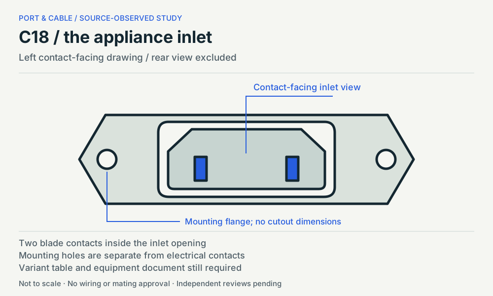
Equipment inlet / screw-mounted series example · Source, view and omissions (private workspace)
The 6102-3 study follows the contact-facing series drawing associated with 6102.3200. Its front outline does not identify rear terminals, a gasket, an equipment model or a compatible retaining mechanism. The separate variant row is part of the identification.
Read the evidence and its limits
Interpower identifies C17/C18 as a Class II pair for applications not requiring a ground path; V40 normalizes that as a two-pole, no-protective-earth boundary. C216B
V40 engineering-reference fact only; independent human review remains pending. This claim does not approve fabrication, rewiring, substitution, electrical safety, protocol support or end-to-end compatibility.
SCHURTER lists 6102.3200 as a screw-mounted, protection-class-II C18 inlet variant with quick-connect terminals; 6102.3100 is separately listed with solder terminals. C216C
Exact variant distinction inside the 6102-3 series. It is not a replacement, termination, sealing or wiring instruction; matching front appearance does not erase variant differences.
The left contact-facing drawing on page 2 of the 6102-3 datasheet shows two blade contacts within the inlet opening and a mounting hole on each side; profile, rear and panel-cutout views are separate. C216D
Qualitative source-facing series drawing for recognition. Rear terminals and cutouts are not reused as the mating face. No dimensions, pin labels, cord-latch notch or installation approval are supplied.
The 6102-3 datasheet states IEC 10 A / 250 VAC at 50 Hz and UL/CSA 15 A / 250 VAC at 60 Hz, and identifies the C18 inlet as protection class II with a 70 °C pin-temperature classification. C216E
Source-specific inlet and approval categories only; not an assembled cord rating, ambient-temperature guarantee or permission to substitute equipment requiring protective earth.
Compare role and observed features, not physical size. These panels use different views and are not to a common scale. No hidden latch geometry, rear wiring or exact mating dimensions are supplied.
02 / SOURCE-SCOPED EXAMPLE
The inlet rating does not become the cord rating.
This is a scope comparison, not a power calculator or approved installation. A broader family page, inlet marking or similar shell cannot upgrade the named 125 VAC cord. The equipment manual, supply conditions and exact assembly documentation still control selection.
03 / CHOOSE THE NEXT DOCUMENT
What is the remaining question?
Identify an unknown end
Keep the device model, label and safely visible connector view together. Use the manual to confirm C17/C18, not trial fitting, probing, opening equipment or energized inspection.
Choose a replacement cord
Start with the equipment maker’s specified cord. Confirm exact assembly ratings, region, plug and required retention. A C17 label alone does not answer those questions.
Read the evidence and its limits
SCHURTER identifies 3-101-794 as a molded C17 V-Lock cord set with a North American NEMA 1-15 plug, 3.0 m black SJT 2x18 AWG cable. C215C
Exact 3-101-794 assembly identification only; not all C17 cables, a bare connector, a rewireable kit or an adapter recommendation.
The 3-101-794 technical-data row states a UL/CSA rating of 10 A / 125 VAC at 50/60 Hz. C215D
Named complete cord assembly and specified approval scope only. An inlet or family-level 250 VAC value cannot be transferred to this cord; equipment and supply suitability remain unresolved.
Understand a release control
The illustrated cord has a visible V-Lock control. The source calls for a matching retention combination. Do not infer that the C18 series drawing includes the required notch or certifies an unknown installation.
Read the evidence and its limits
The 3-101-794 datasheet photograph shows two recessed openings on the C17 cord end and a visible top release control; its V-Lock note requires a matching retention combination. C215E
Photo-observed oblique recognition only. No straight-on or measured mating geometry is inferred from the symbol, and a visible button does not prove locking compatibility with an unspecified inlet.
The left contact-facing drawing on page 2 of the 6102-3 datasheet shows two blade contacts within the inlet opening and a mounting hole on each side; profile, rear and panel-cutout views are separate. C216D
Qualitative source-facing series drawing for recognition. Rear terminals and cutouts are not reused as the mating face. No dimensions, pin labels, cord-latch notch or installation approval are supplied.
Identify a component variant
Read the order number alongside the drawing. The source distinguishes quick-connect 6102.3200 from solder-terminal 6102.3100; a front view does not establish a replacement or termination method.
Read the evidence and its limits
SCHURTER lists 6102.3200 as a screw-mounted, protection-class-II C18 inlet variant with quick-connect terminals; 6102.3100 is separately listed with solder terminals. C216C
Exact variant distinction inside the 6102-3 series. It is not a replacement, termination, sealing or wiring instruction; matching front appearance does not erase variant differences.
04 / COMMON QUESTIONS
What the silhouette cannot decide.
CHECK 01
Which one is on the cord?
C17 names the cord connector; C18 names the appliance inlet. The two studies show different roles and different views, not two interchangeable parts.
Read the evidence and its limits
SCHURTER identifies 3-101-794 as a molded C17 V-Lock cord set with a North American NEMA 1-15 plug, 3.0 m black SJT 2x18 AWG cable. C215C
Exact 3-101-794 assembly identification only; not all C17 cables, a bare connector, a rewireable kit or an adapter recommendation.
SCHURTER lists 6102.3200 as a screw-mounted, protection-class-II C18 inlet variant with quick-connect terminals; 6102.3100 is separately listed with solder terminals. C216C
Exact variant distinction inside the 6102-3 series. It is not a replacement, termination, sealing or wiring instruction; matching front appearance does not erase variant differences.
CHECK 02
Does the missing earth position mean a damaged C13/C14?
C17/C18 is a documented Class II, non-grounded pair. Do not diagnose a broken or intentionally removable earth contact from resemblance. Confirm the exact equipment designation; never remove an earth contact or substitute this pair for equipment that requires it.
Read the evidence and its limits
Interpower identifies C17/C18 as a Class II pair for applications not requiring a ground path; V40 normalizes that as a two-pole, no-protective-earth boundary. C215B
V40 engineering-reference fact only; independent human review remains pending. This claim does not approve fabrication, rewiring, substitution, electrical safety, protocol support or end-to-end compatibility.
Interpower identifies C17/C18 as a Class II pair for applications not requiring a ground path; V40 normalizes that as a two-pole, no-protective-earth boundary. C216B
V40 engineering-reference fact only; independent human review remains pending. This claim does not approve fabrication, rewiring, substitution, electrical safety, protocol support or end-to-end compatibility.
CHECK 03
Does a 250 VAC inlet make this a 250 VAC cord?
No. The named 3-101-794 complete cord is listed at 10 A / 125 VAC under UL/CSA. The 6102-3 inlet has separately scoped IEC and UL/CSA ratings. Keep the cord, inlet, device and supply requirements separate; this comparison does not approve an installation.
Read the evidence and its limits
The 3-101-794 technical-data row states a UL/CSA rating of 10 A / 125 VAC at 50/60 Hz. C215D
Named complete cord assembly and specified approval scope only. An inlet or family-level 250 VAC value cannot be transferred to this cord; equipment and supply suitability remain unresolved.
The 6102-3 datasheet states IEC 10 A / 250 VAC at 50 Hz and UL/CSA 15 A / 250 VAC at 60 Hz, and identifies the C18 inlet as protection class II with a 70 °C pin-temperature classification. C216E
Source-specific inlet and approval categories only; not an assembled cord rating, ambient-temperature guarantee or permission to substitute equipment requiring protective earth.
CHECK 04
Does every C18 inlet accept the visible locking feature?
The V-Lock note calls for a matching retention combination. Neither the C18 designation nor the generic series front drawing certifies the lock for an unspecified inlet. Confirm the exact retaining system in the equipment and accessory documentation.
Read the evidence and its limits
The 3-101-794 datasheet photograph shows two recessed openings on the C17 cord end and a visible top release control; its V-Lock note requires a matching retention combination. C215E
Photo-observed oblique recognition only. No straight-on or measured mating geometry is inferred from the symbol, and a visible button does not prove locking compatibility with an unspecified inlet.
The left contact-facing drawing on page 2 of the 6102-3 datasheet shows two blade contacts within the inlet opening and a mounting hole on each side; profile, rear and panel-cutout views are separate. C216D
Qualitative source-facing series drawing for recognition. Rear terminals and cutouts are not reused as the mating face. No dimensions, pin labels, cord-latch notch or installation approval are supplied.
CHECK 05
Can the front view determine the rear connection?
No. The 6102-3 sheet separates contact-facing, rear, profile and panel-cutout views. Its variant table distinguishes quick-connect and solder versions. No rear wiring or cutout dimensions are supplied by this recognition reference.
Read the evidence and its limits
SCHURTER lists 6102.3200 as a screw-mounted, protection-class-II C18 inlet variant with quick-connect terminals; 6102.3100 is separately listed with solder terminals. C216C
Exact variant distinction inside the 6102-3 series. It is not a replacement, termination, sealing or wiring instruction; matching front appearance does not erase variant differences.
The left contact-facing drawing on page 2 of the 6102-3 datasheet shows two blade contacts within the inlet opening and a mounting hole on each side; profile, rear and panel-cutout views are separate. C216D
Qualitative source-facing series drawing for recognition. Rear terminals and cutouts are not reused as the mating face. No dimensions, pin labels, cord-latch notch or installation approval are supplied.
CHECK 06
Is 70 °C a room-temperature allowance?
The C18 source labels 70 °C as a pin-temperature classification and separately lists operating conditions. It is not a blanket ambient-temperature or device approval. Use the exact component and equipment documents.
Read the evidence and its limits
The 6102-3 datasheet states IEC 10 A / 250 VAC at 50 Hz and UL/CSA 15 A / 250 VAC at 60 Hz, and identifies the C18 inlet as protection class II with a 70 °C pin-temperature classification. C216E
Source-specific inlet and approval categories only; not an assembled cord rating, ambient-temperature guarantee or permission to substitute equipment requiring protective earth.
A COMPACT REFERENCE TO KEEP
Roles, ratings and linked sources.
Letter PDF (legacy download held for current evidence review). Current focused printable references · A4 PDF (legacy download held for current evidence review). Current focused printable references
Three pages in each edition. Qualitative original studies, exact scope labels and the next documents to check. Private review edition, not electrical work instructions.