
PORT & CABLE / COMPACT IEC REFERENCE
Know the cord.
Know the inlet.
Four existing references. Separate the cord-side connector from the equipment inlet before reading a rating.
Source-scoped qualitative studies, not inspected hardware, mating gauges, wiring diagrams or appliance approval. The damaged V144 archive prevents certification of its original source code; source observations below are inherited, not repeated in V145.
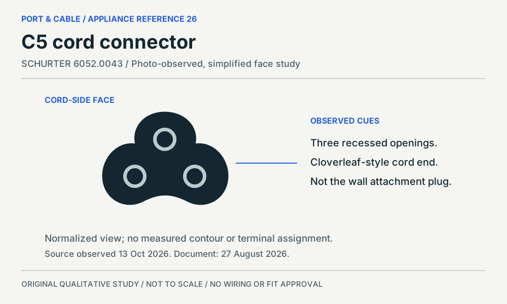
Cord-side connector
C5 cord connector
Three recessed openings in a cloverleaf-style cord end.
SCHURTER 6052.0043 · observed document 27 August 2026.
The cord connector is not the wall plug. Read the appliance or power-supply input label, the approved cord specification and the local plug requirements separately.
Not established: No universal C5 current rating, inspected cable, terminal map, exact housing dimensions or approval for a particular appliance.
Read the inherited source findings
SCHURTER identifies 6052.0043 as a cord set with a straight C5 connector; its photograph shows three recessed contact openings. C211C
For 6052.0043, SCHURTER lists UL/CSA 7 A at 125 VAC, 50/60 Hz. This is the named cord-set rating, not a universal C5 limit. C211D
The 6052.0043 sheet lists protection class I and 70 °C pin temperature; its separate operating-temperature field is −40 °C to 70 °C. C211E
The 6052.0043 variant row distinguishes the C5 connector from the North American NEMA 5-15 plug at the other end of the cord. C211F
PDF pp.1–2: p.1 photograph, connector symbol and product data; p.2 variant table and dated footer (27.08.2026).
S601 · SCHURTER source ↗View the original study and its limitations → (private workspace)
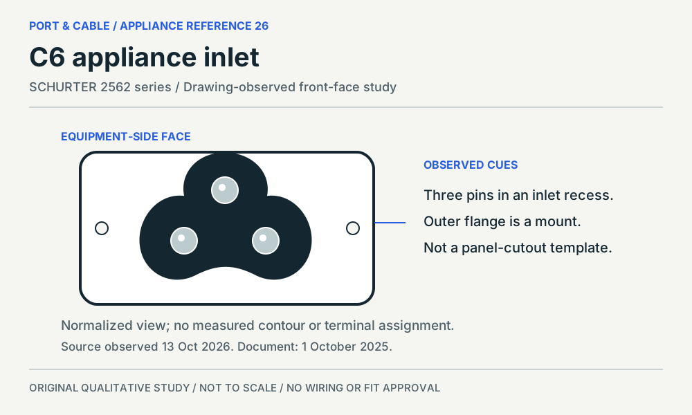
Equipment-side inlet
C6 appliance inlet
Three pins inside a cloverleaf-style recessed inlet.
SCHURTER 2562 series · observed document 1 October 2025.
The panel outline is not the mating opening. Match the exact inlet series and appliance documentation. Keep its mating face, mounting cutout and rear terminal variant distinct.
Not established: No panel-cutout template, installation method, wiring assignment, contact gauge or device safety certification.
Read the inherited source findings
SCHURTER 2562 is a screw-mounted C6 appliance inlet. Its front drawing depicts three pins within the coupler recess, distinct from the mounting flange. C212C
The 2562 sheet separates IEC 2.5 A / 250 VAC at 50 Hz from UL/CSA 7 A / 125 VAC at 60 Hz; these are different listed rating schemes. C212D
SCHURTER lists the 2562 for protection-class-I appliances and gives 70 °C pin temperature; operating temperature is separately stated as −25 °C to 70 °C. C212E
The 2562 drawing separates component views from panel cutouts and shows solder/quick-connect and PCB variants. The inlet designation alone does not specify its rear termination. C212F
PDF p.1 photo and data; p.3 front/side component views and separate panel cutouts; p.4 terminal variants and footer (01.10.2025).
S602 · SCHURTER source ↗View the original study and its limitations → (private workspace)
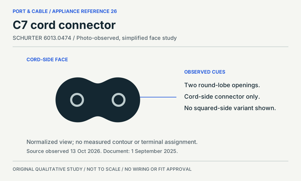
Cord-side connector
C7 cord connector
Two round lobes with recessed openings on the cord end.
SCHURTER 6013.0474 · observed document 1 September 2025.
This study is the two-round-lobe example. Check the exact inlet shape and equipment-approved cord. Do not assume that a differently keyed or squared-side variant is covered by this study.
Not established: No polarized-variant equivalence, appliance input-voltage conversion, terminal mapping or replacement-cord approval.
Read the inherited source findings
SCHURTER 6013.0474 is a straight C7 cord-set example; its photograph and symbol show a two-round-lobe connector, not a squared-side variant. C213C
For 6013.0474, SCHURTER lists IEC 2.5 A at 250 VAC, 50 Hz. This describes the named cord set, not the input range of an appliance. C213D
The 6013.0474 sheet lists protection class II and 70 °C pin temperature, separately from an operating-temperature range of −25 °C to 70 °C. C213E
The 6013.0474 sheet identifies an EN 50075 plug at the other end and lists 2572 among its C8 mating-inlet families. It does not identify a particular appliance. C213F
PDF p.1 product photograph, two-round-lobe symbol and data; p.2 variant/mating-inlet tables and dated footer (01.09.2025).
S603 · SCHURTER source ↗View the original study and its limitations → (private workspace)
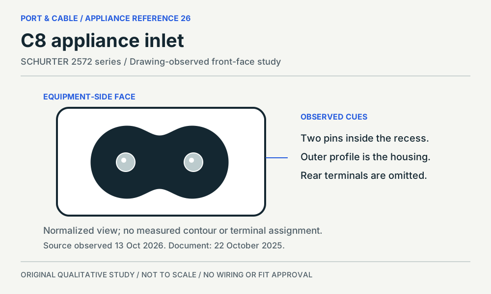
Equipment-side inlet
C8 appliance inlet
Two pins inside a recessed, waist-shaped inlet opening.
SCHURTER 2572 series · observed document 22 October 2025.
The housing, recess and pins are different features. Use the equipment documentation to identify the inlet variant and approved cord; the study does not cover every C8-associated housing or mounting option.
Not established: No mounting gauge, rear-terminal map, universal current limit, polarized-variant approval or safe-mating verdict.
Read the inherited source findings
SCHURTER 2572 is an insert-mounted C8 inlet family; the front drawing shows two pins inside the recessed interface and a separate outer mounting profile. C214C
The 2572 sheet lists IEC 2.5 A / 250 VAC at 50 Hz and UL/CSA 7 A / 125 VAC at 60 Hz as separate product-rating entries. C214D
SCHURTER describes the 2572 as suitable for protection-class-II appliances with 70 °C pin temperature; its separate operating-temperature field is −25 °C to 70 °C. C214E
The 2572 drawing distinguishes the mating face, rear terminal orientations and panel cutout; its mating-connector list includes C7 cord example 6013.0474. C214F
PDF p.1 product photo/data; p.2 front and side component drawings plus separate panel cutout; p.4 variants, cord examples and footer (22.10.2025).
S604 · SCHURTER source ↗View the original study and its limitations → (private workspace)
Keep the component and equipment questions separate.
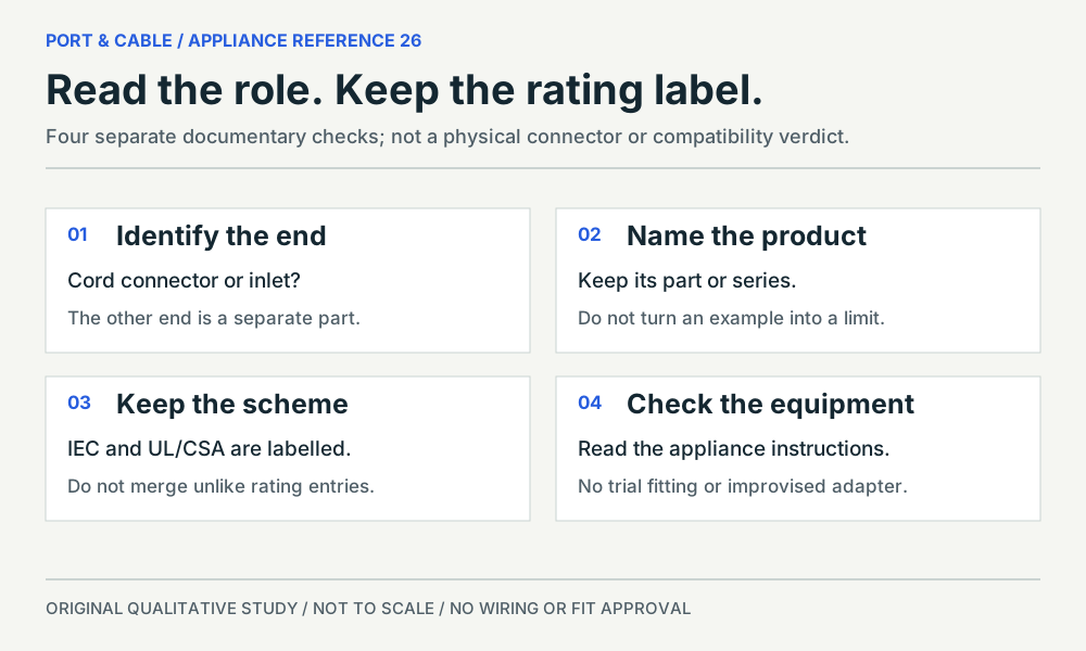
A source-specific rating is not a universal rating for every similarly named connector. The two-round-lobe C7 study does not cover every polarized or differently keyed variant.
The original V144 print references
These three-page PDFs were recovered intact and retained byte-for-byte. Their historical source-observation declarations do not establish new V145 review.
Letter reference ↓ (legacy download held for current evidence review). Current focused printable references · A4 reference ↓ (legacy download held for current evidence review). Current focused printable references