FIELD GUIDESource-led reference

P112 / Telephone / Connector

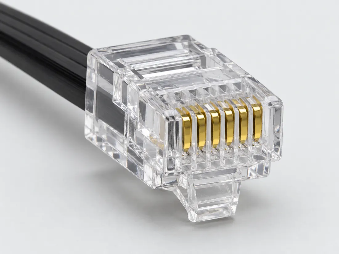
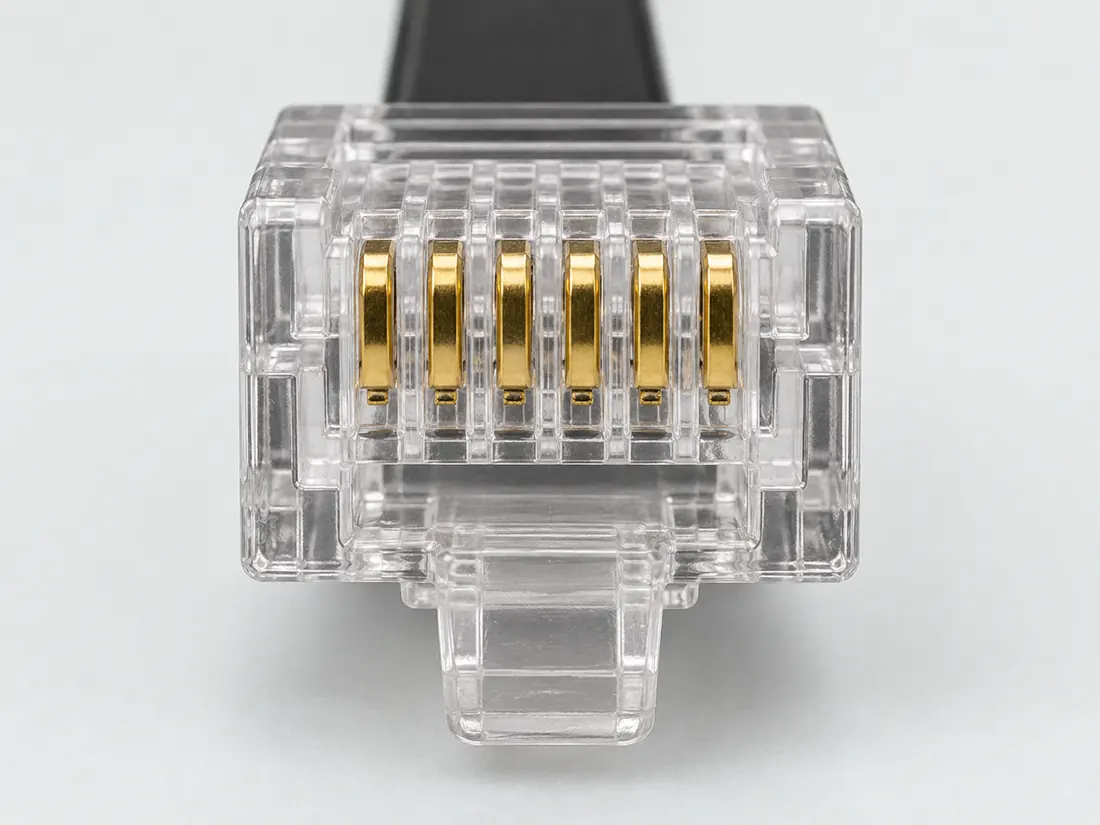
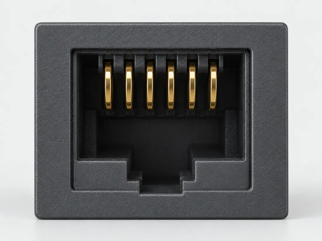
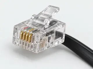
6P6C modular plug (often sold as RJ12)

The six-position, six-contact modular form is often sold as RJ12; the equipment determines its actual function.

Also called RJ12 RJ-12 6 position 6 contact

Same position count can hide a different populated layout.

Look for

Compare the six populated contacts with the six-position housing; keep the port role separate from this observation.

Claim inspection dates: 2026-10-03 · Independent review pending

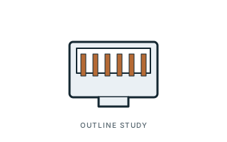
Inspect the illustrationFront-oriented modular sketch · larger view & look-alikes
6P6C modular plug (often sold as RJ12) — front-oriented modular sketch; role not specified; original, not-to-scale identification schematic; drawing review pending
View Front-oriented modular sketchDepiction Role not specifiedNot to scale · independent drawing review pending

Read the view

Six filled contact marks within a six-position outline

The latch-like projection is drawn at the bottom; no terminated-wire view or pin-number direction is supplied.

About the marks: Contact population is separate from signal assignment.

What it cannot establish: A shared housing is not proof of the same wiring, service or device role.

Enlargement changes display size only. It does not reveal measured geometry, a pin assignment or an approved mating combination.

Compare a likely look-alike

Read the underlying references: S091. Artwork interpretation remains review-pending.

How to read connector illustrations →

The useful distinction

Recognize it. Then verify it.

The six-position, six-contact modular form is often sold as RJ12; the equipment determines its actual function. [C112A]

Its documented uses extend beyond a single uniform telephone application. [C112B]

Source-scoped identification facts

Each value retains its exact example, role and measurement axis. Facts from different parts must not be combined into an invented component.

Documented examples; not a mating drawing or compatibility approval
Nominal contacts6S091Nominal contact count; some implementations may omit populated positions. It is not a wiring map.
Positions / cavity span6 (Claim C112A)S091Recorded source-scoped values; named examples do not describe every family variant or establish compatibility. Identification and explicitly scoped documentation only; not an end-to-end connection approval
Connector roleplug (135-0341)S923Named source examples retain separate role, part, view and axis limits; values are not a universal family specification. 135-0341. Documented role: plug. Flat26AWG is accepted wire, not connector pitch or housing dimension. Generic4–8position wording does not transfer8position non-keyed attribute to other forms.
ManufacturerPrimex (135-0341)S923Named source examples retain separate role, part, view and axis limits; values are not a universal family specification. 135-0341. Documented role: plug. Flat26AWG is accepted wire, not connector pitch or housing dimension. Generic4–8position wording does not transfer8position non-keyed attribute to other forms.
SeriesModular Plugs (135-0341)S923Named source examples retain separate role, part, view and axis limits; values are not a universal family specification. 135-0341. Documented role: plug. Flat26AWG is accepted wire, not connector pitch or housing dimension. Generic4–8position wording does not transfer8position non-keyed attribute to other forms.
Exact part / implementation135-0341 (135-0341)S923Named source examples retain separate role, part, view and axis limits; values are not a universal family specification. 135-0341. Documented role: plug. Flat26AWG is accepted wire, not connector pitch or housing dimension. Generic4–8position wording does not transfer8position non-keyed attribute to other forms.

Not recorded: Populated contacts, Contact rows, Contact pitch, Dimensions / axis, Contact gender / arrangement, Mounting, Coupling / latch, Keying / polarization, Shell / form, Recorded markings, View convention. Unknown fields stay unknown; illustrations supply no measurements or pin assignments.

Recorded variant and source limits
  • Check the exact device manual before wiring or applying power.
  • Microchip MPLAB ICD 3 target-board 6-pin modular connector (Microchip calls it 'RJ-11'): Bottom view of target PCB per Figures 2-3 and B-2.
  • FCC registered jack RJ18C / RJ18W (single line with make-busy): 47 CFR 68.502 diagram position numbering.
  • Microchip MPLAB ICD 5 legacy 6-pin RJ-11 cable, target side, ICSP: Microchip Table 3-2 '6-Pin Modular Connector' numbering.
Report a correction to these facts →

Bounded facts, visible unknowns

Specifications and limits

6P6C modular plug (often sold as RJ12) facts and limitations
Documented identificationThe guide identifies the common RJ12 form as six positions with six conductors in one row. [C112A]
Important distinctionIts documented uses extend beyond a single uniform telephone application. [C112B]
Mechanical dimensionsNo independently approved mechanical dimensions. Do not use this record for fabrication or fit testing.
Engineering pinoutSource-checked engineering profile available; independent review pending. Open engineering profile →
Verified device listNot included. Check exact device and accessory documentation.
A boundary, not an omission to guess around.

Record the exact device model and the label beside the port. Obtain its manual and the accessory documentation. Keep unknown properties unknown instead of filling them from a visually similar item.

Before you connect

What to check

  1. Write down the equipment model and socket label.
  2. Count contacts rather than relying on the RJ trade name.
  3. Obtain the manufacturer cable specification before connecting.
Trace a supported connection class →

Pins & wiring

Pinout

Choose the exact wiring. Pin numbers follow its stated view; a schematic does not establish physical positions. Check your exact device before wiring.

What the status labels mean
Confirmed
Recorded research passes agree within this variant; this is not independent human review or hardware validation.
Single source
Only one underlying document, or one pass, supports this assignment.
Device-specific
Supported for the named equipment or wiring only. Check your device’s manual.
Unverified
Missing or conflicting evidence. Do not wire from this row.
Not connected
The source explicitly says NC, no contact or no pin for this wiring.
Wiring variant

Microchip MPLAB ICD 3 target-board 6-pin modular connector (Microchip calls it 'RJ-11')

Device-specific wiring. Check your device’s manual before connecting or applying power.

View and evidence limits

Bottom view of target PCB per Figures 2-3 and B-2.

  • P112 6P6C ("RJ12") — **No overlap: different variants** — Pass A: Microchip ICD 3 target jack. Pass B: FCC RJ18C plus Microchip ICD 5. ICD 3 and ICD 5 agree on pins 1–5 (MCLR/Vpp, VDD, GND, PGD, PGC); pin 6 differs by tool (LVP/PGM vs TAUX), as expected for device-specific wiring. **Neither pass could source the common retail telephone "RJ12" wiring** (RJ12C/RJ25C); TIA-1096-A is paywalled.
  • Device-specific programming/debug interface, not a telephone wiring standard.
  • Microchip notes cable connections at the debugger and target are mirror images (pin 1 at one end meets pin 6 at the other end).
  • Neither USOC appears in 47 CFR 68.502 (1996-2000 editions checked); the current description (TIA-1096-A) is paywalled and was not inspected.
  • Microchip specifies AMP 555165-1 and a six-conductor cable; the AMP drawing itself was not inspected.
6P6C modular (RJ12) engineering referenceBottom view of target PCB per Figures 2-3 and B-2.SCHEMATIC · physical positions unconfirmedNot to scale · check the named wiring and device manual1: VPP/MCLR (device_specific)12: VDD (Target) (device_specific)23: VSS (Ground) (device_specific)34: PGD (RB7) (device_specific)45: PGC (RB6) (device_specific)56: LVP / PGM (device_specific)6powergrounddataConfigshieldNCUnknown
Schematic only · physical contact positions unconfirmed. Original drawing · not to scale. Scroll sideways if needed.
Microchip MPLAB ICD 3 target-board 6-pin modular connector (Microchip calls it 'RJ-11') — source-scoped contact map
PinSignalWhat it doesStatus
1VPP/MCLRControl, detection or configuration connection; check the source and device.Device-specific
Sources
2VDD (Target)Power connection (VDD (Target)). Check the specified supply.Device-specific
Sources
3VSS (Ground)Ground reference and return.Device-specific
Sources
4PGD (RB7)Control, detection or configuration connection; check the source and device.Device-specific
Sources
5PGC (RB6)Control, detection or configuration connection; check the source and device.Device-specific
Sources
6LVP / PGMControl, detection or configuration connection; check the source and device.Device-specific
Sources
Sources (1)

FCC registered jack RJ18C / RJ18W (single line with make-busy)

Device-specific wiring. Check your device’s manual before connecting or applying power.

View and evidence limits

47 CFR 68.502 diagram position numbering.

  • P112 6P6C ("RJ12") — **No overlap: different variants** — Pass A: Microchip ICD 3 target jack. Pass B: FCC RJ18C plus Microchip ICD 5. ICD 3 and ICD 5 agree on pins 1–5 (MCLR/Vpp, VDD, GND, PGD, PGC); pin 6 differs by tool (LVP/PGM vs TAUX), as expected for device-specific wiring. **Neither pass could source the common retail telephone "RJ12" wiring** (RJ12C/RJ25C); TIA-1096-A is paywalled.
  • Neither RJ12C (key-telephone A/A1 leads) nor RJ25C (three-line) appears in the 10-1-00 edition of 47 CFR 68.502, and TIA-1096-A is paywalled, so the configurations behind the retail name 'RJ12' were not verified.
  • Microchip Table 3-3 shows that the UART TX/RX lines sit on 8-pin positions that the 6-pin cable does not carry; not mapped.
6P6C modular (RJ12) engineering reference47 CFR 68.502 diagram position numbering.SCHEMATIC · physical positions unconfirmedNot to scale · check the named wiring and device manual1: MB (device_specific)12: Reserved (device_specific)23: R (ring) (device_specific)34: T (tip) (device_specific)45: Reserved (device_specific)56: MB1 (device_specific)6powergrounddataConfigshieldNCUnknown
Schematic only · physical contact positions unconfirmed. Original drawing · not to scale. Scroll sideways if needed.
FCC registered jack RJ18C / RJ18W (single line with make-busy) — source-scoped contact map
PinSignalWhat it doesStatus
1MBControl, detection or configuration connection; check the source and device.Device-specific
Sources
2ReservedReserved; no general-purpose wiring is established.Device-specific
Sources
3R (ring)Control, detection or configuration connection; check the source and device.Device-specific
Sources
4T (tip)Control, detection or configuration connection; check the source and device.Device-specific
Sources
5ReservedReserved; no general-purpose wiring is established.Device-specific
Sources
6MB1Control, detection or configuration connection; check the source and device.Device-specific
Sources
Sources (1)

Microchip MPLAB ICD 5 legacy 6-pin RJ-11 cable, target side, ICSP

Device-specific wiring. Check your device’s manual before connecting or applying power.

View and evidence limits

Microchip Table 3-2 '6-Pin Modular Connector' numbering.

  • P112 6P6C ("RJ12") — **No overlap: different variants** — Pass A: Microchip ICD 3 target jack. Pass B: FCC RJ18C plus Microchip ICD 5. ICD 3 and ICD 5 agree on pins 1–5 (MCLR/Vpp, VDD, GND, PGD, PGC); pin 6 differs by tool (LVP/PGM vs TAUX), as expected for device-specific wiring. **Neither pass could source the common retail telephone "RJ12" wiring** (RJ12C/RJ25C); TIA-1096-A is paywalled.
  • Neither RJ12C (key-telephone A/A1 leads) nor RJ25C (three-line) appears in the 10-1-00 edition of 47 CFR 68.502, and TIA-1096-A is paywalled, so the configurations behind the retail name 'RJ12' were not verified.
  • Microchip Table 3-3 shows that the UART TX/RX lines sit on 8-pin positions that the 6-pin cable does not carry; not mapped.
6P6C modular (RJ12) engineering referenceMicrochip Table 3-2 '6-Pin Modular Connector' numbering.SCHEMATIC · physical positions unconfirmedNot to scale · check the named wiring and device manual1: MCLR/Vpp (TVPP) (device_specific)12: VDD (TVDD) (device_specific)23: GND (device_specific)34: PGD (ICSP DAT) (device_specific)45: PGC (ICSP CLK) (device_specific)56: TAUX (device_specific)6powergrounddataConfigshieldNCUnknown
Schematic only · physical contact positions unconfirmed. Original drawing · not to scale. Scroll sideways if needed.
Microchip MPLAB ICD 5 legacy 6-pin RJ-11 cable, target side, ICSP — source-scoped contact map
PinSignalWhat it doesStatus
1MCLR/Vpp (TVPP)Control, detection or configuration connection; check the source and device.Device-specific
Sources
2VDD (TVDD)Power connection (VDD (TVDD)). Check the specified supply.Device-specific
Sources
3GNDGround reference and return.Device-specific
Sources
4PGD (ICSP DAT)Control, detection or configuration connection; check the source and device.Device-specific
Sources
5PGC (ICSP CLK)Clock or clock-control connection, as named by this source.Device-specific
Sources
6TAUXControl, detection or configuration connection; check the source and device.Device-specific
Sources
Sources (1)

What is not established

This field note does not approve a connection, publish a pinout or provide a measured template. Use the linked source scope and the checklist as a documentation starting point.

Your next step

Move from the form to the requirement.

The source trail

Evidence for this page

AI-assisted inspection is not independent engineering review. Source scope and access limitations are disclosed below. Procedural checklists are editorial requirements, not hardware measurements.

Back to first citation ↑
C112ASource checked · pending review

The guide identifies the common RJ12 form as six positions with six conductors in one row.

C2G / Legrand · Modular connector identification guide ↗

Locator: 6-pin RJ-12; 4-pin RJ-11; RJ-22
Access: public page. Trade names are not exact registered-jack wiring declarations. No telephone voltage, line count, crimping or network-speed inference.

S091: full source recordInspect review dependencies → (private workspace)

Claim scope: Identification and explicitly scoped documentation only; not an end-to-end connection approval. Next review due 2027-01-01.

Back to first citation ↑
C112BSource checked · pending review

Its documented uses extend beyond a single uniform telephone application.

C2G / Legrand · Modular connector identification guide ↗

Locator: 6-pin RJ-12; 4-pin RJ-11; RJ-22
Access: public page. Trade names are not exact registered-jack wiring declarations. No telephone voltage, line count, crimping or network-speed inference.

S091: full source recordInspect review dependencies → (private workspace)

Claim scope: Identification and explicitly scoped documentation only; not an end-to-end connection approval. Next review due 2027-01-01.

Suggest a correction to this field note →

Put this field note to work.

Add to discovery trayRecord an unsaved candidate (private workspace)

Compare look-alikes: Telephone modular forms

Candidate selection does not confirm the identity or capabilities of your physical item.

Evidence behind this page

Scope first. Source second. Approval separate.

1 linked sources · 2 scoped claims · 0 sources with inspection/access flags.

Page scope: consumer_reference_expansion

Assessment 2026-10-22 · earliest scheduled source review 2027-01-01. This is a recorded-date assessment, not a live source check. Page-level independent review is not established by this panel.

Inspect 1 source scopes, access limits and dates

S091 · Modular connector identification guide

C2G / Legrand · Manufacturer / product-owner domain · inspected 2026-10-03 · due 2027-01-01

Within inspection window

Scoped support: 6P6C, common 6P4C trade naming, and the four-position handset form.

Not established / limitations: Trade names are not exact registered-jack wiring declarations. No telephone voltage, line count, crimping or network-speed inference.

Locator: 6-pin RJ-12; 4-pin RJ-11; RJ-22

Trace 2 claims to their source records

C112A · P112

The guide identifies the common RJ12 form as six positions with six conductors in one row.

Claim scope: Identification and explicitly scoped documentation only; not an end-to-end connection approval

Source links: S091 · Evidence trail → (private workspace)

C112B · P112

Its documented uses extend beyond a single uniform telephone application.

Claim scope: Identification and explicitly scoped documentation only; not an end-to-end connection approval

Source links: S091 · Evidence trail → (private workspace)

Prepare this page for review → (private workspace)Read the evidence method →

Recorded evidence only. An inspection date, publisher label, source link or generated packet is not independent technical review, hardware testing, fabrication approval or a compatibility verdict.