FIELD GUIDESource-led reference

P110 / Audio / Connector

5-pin DIN connector: MIDI and legacy uses

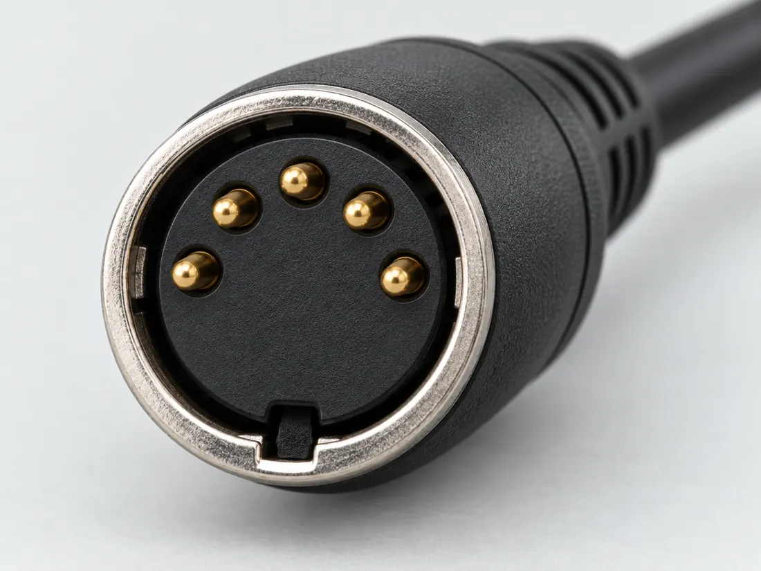
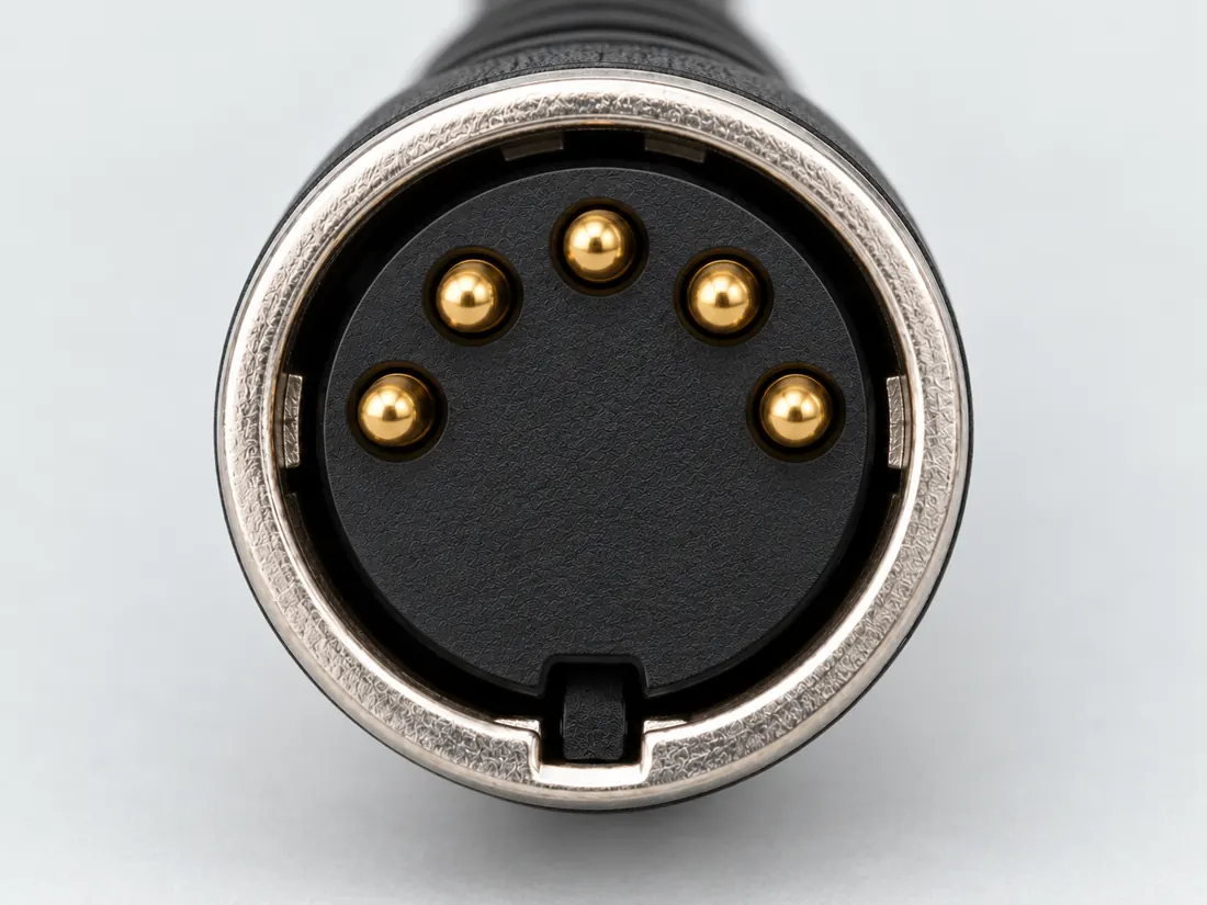
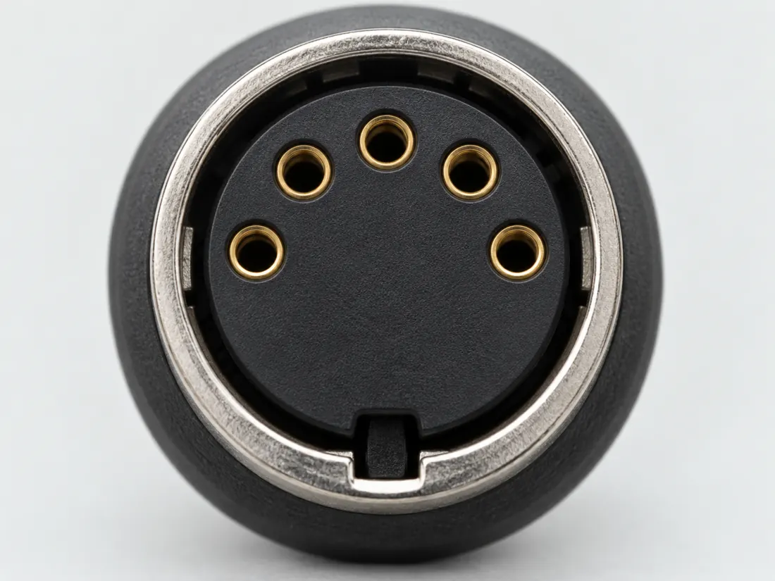
A five-pin DIN shell appears in MIDI and legacy computer contexts; the shell alone does not identify the application.

Also called MIDI DIN 5 pin DIN AT keyboard plug

MIDI is a transport context, not every DIN socket.

Look for

Read the DIN marking and device role. Compare the arrangement in the manual rather than assuming all five-pin circular connectors are alike.

Claim inspection dates: 2026-10-03, 2026-10-13 · Independent review pending

Image inspection / P110

See the view. Check its scope.

1 registered view for this reference. Different part examples are not automatically mates; all remain not to scale and independently unapproved.

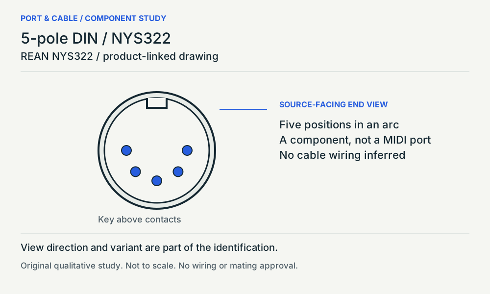
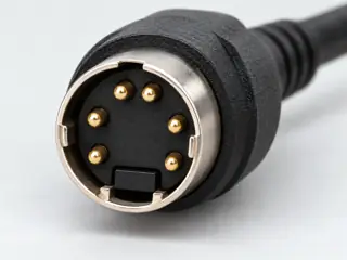
5-pole DIN / NYS322. Source-facing end view / key above contacts. Five positions across the lower arc; Upper key; no contact numbering; The part source does not establish MIDI service. Original qualitative study, not a pinout. (private workspace)

P110 / Source-observed physical study

5-pole DIN / NYS322

REAN NYS322 / product-linked drawing

Source-facing end view / key above contacts · Cable plug / cable end

Not to scale. Technical and rights review pending.

Inspect view & provenance (private workspace)

The useful distinction

Recognize it. Then verify it.

A five-pin DIN shell appears in MIDI and legacy computer contexts; the shell alone does not identify the application. [C110A]

The MIDI Association separately specifies a MIDI transport using five-pin DIN. [C110B]

REAN identifies NYS322 as a male five-pole DIN cable component; its linked end view places the five contacts in a lower arc below the key. [C110C]

Source-scoped identification facts

Each value retains its exact example, role and measurement axis. Facts from different parts must not be combined into an invented component.

Documented examples; not a mating drawing or compatibility approval
Nominal contacts5S089Nominal contact count; some implementations may omit populated positions. It is not a wiring map.
Connector roleplug (NYS322)S617Named source examples retain separate role, part, view and axis limits; values are not a universal family specification. NYS322. Documented role: plug. 6.5mmmaximum cableOD is wire acceptance,not shell diameter.; NYS322drawingS618full text provides59.5,13.35diameter,16diameter but axes not visually verified after503; these are not adopted as geometry.; Gold-platedNYS322G andgold-shellNYS322AG variants stay separate; no MIDI circuit map from physical5pin form.
ManufacturerREAN (NYS322)S617Named source examples retain separate role, part, view and axis limits; values are not a universal family specification. NYS322. Documented role: plug. 6.5mmmaximum cableOD is wire acceptance,not shell diameter.; NYS322drawingS618full text provides59.5,13.35diameter,16diameter but axes not visually verified after503; these are not adopted as geometry.; Gold-platedNYS322G andgold-shellNYS322AG variants stay separate; no MIDI circuit map from physical5pin form.
SeriesNYS322 DIN (NYS322)S617Named source examples retain separate role, part, view and axis limits; values are not a universal family specification. NYS322. Documented role: plug. 6.5mmmaximum cableOD is wire acceptance,not shell diameter.; NYS322drawingS618full text provides59.5,13.35diameter,16diameter but axes not visually verified after503; these are not adopted as geometry.; Gold-platedNYS322G andgold-shellNYS322AG variants stay separate; no MIDI circuit map from physical5pin form.
Exact part / implementationNYS322 (NYS322)S617Named source examples retain separate role, part, view and axis limits; values are not a universal family specification. NYS322. Documented role: plug. 6.5mmmaximum cableOD is wire acceptance,not shell diameter.; NYS322drawingS618full text provides59.5,13.35diameter,16diameter but axes not visually verified after503; these are not adopted as geometry.; Gold-platedNYS322G andgold-shellNYS322AG variants stay separate; no MIDI circuit map from physical5pin form.

Not recorded: Positions / cavity span, Populated contacts, Contact rows, Contact pitch, Dimensions / axis, Contact gender / arrangement, Mounting, Coupling / latch, Keying / polarization, Shell / form, Recorded markings, View convention. Unknown fields stay unknown; illustrations supply no measurements or pin assignments.

Recorded variant and source limits
  • Check the exact device manual before wiring or applying power.
  • MIDI 1.0 OUT (and optional THRU) jack, 5-pin 180-degree DIN female, CA-033: Pin numbers as drawn in CA-033 Figures 1-2 (DIN numbering 1-3-5-2-4 arc); the figures are schematic, not a dimensioned face view.
  • MIDI 1.0 IN jack, 5-pin 180-degree DIN female, CA-033: As for midi-out-thru.
  • IBM Personal Computer AT keyboard connector (system board J22) and keyboard cable DIN: IBM states pin numbering is shown in the Keyboard section; this pass relied on the text tables only, so no spatial face view is asserted.
  • MIDI 1.0 OUT jack (MMA CA-033): Use DIN contact numbers 1-5 (180-degree layout). Spatial positions are not transferred from any figure; MIDI device jacks are female, cables male (CA-033 p. 3).
  • MIDI 1.0 IN jack (MMA CA-033): Use DIN contact numbers 1-5 (180-degree layout). Spatial positions are not transferred from any figure; MIDI device jacks are female, cables male (CA-033 p. 3).
  • MIDI 1.0 THRU jack, optional (MMA CA-033): Use DIN contact numbers 1-5 (180-degree layout). Spatial positions are not transferred from any figure; MIDI device jacks are female, cables male (CA-033 p. 3).
  • IBM Personal Computer AT keyboard connector J22 (system board) / keyboard cable DIN end: Use DIN contact numbers 1-5 (180-degree layout). Spatial positions are not transferred from any figure; MIDI device jacks are female, cables male (CA-033 p. 3).
  • PC AT keyboard 5-pin DIN as tabulated in Atmel AVR313: Use DIN contact numbers 1-5 (180-degree layout). Spatial positions are not transferred from any figure; MIDI device jacks are female, cables male (CA-033 p. 3).
Report a correction to these facts →

Bounded facts, visible unknowns

Specifications and limits

5-pin DIN connector: MIDI and legacy uses facts and limitations
Documented identificationThe DIN guide describes a five-pin circular connector used by older AT-style keyboards. [C110A]
Important distinctionThe MIDI Association separately specifies a MIDI transport using five-pin DIN. [C110B]
Source-observed V148 component scopeREAN NYS322 male DIN component, not an identified MIDI device port. [C110C]
Mechanical dimensionsNo independently approved mechanical dimensions. Do not use this record for fabrication or fit testing.
Engineering pinoutSource-checked engineering profile available; independent review pending. Open engineering profile →
Verified device listNot included. Check exact device and accessory documentation.
A boundary, not an omission to guess around.

Record the exact device model and the label beside the port. Obtain its manual and the accessory documentation. Keep unknown properties unknown instead of filling them from a visually similar item.

Before you connect

What to check

  1. Read MIDI IN, OUT or THRU markings when present.
  2. Confirm the device uses the documented DIN arrangement.
  3. Check the exact adapter specification for any TRS MIDI connection.
Trace a supported connection class →

Pins & wiring

Pinout

Choose the exact wiring. Pin numbers follow its stated view; a schematic does not establish physical positions. Check your exact device before wiring.

What the status labels mean
Confirmed
Recorded research passes agree within this variant; this is not independent human review or hardware validation.
Single source
Only one underlying document, or one pass, supports this assignment.
Device-specific
Supported for the named equipment or wiring only. Check your device’s manual.
Unverified
Missing or conflicting evidence. Do not wire from this row.
Not connected
The source explicitly says NC, no contact or no pin for this wiring.
Wiring variant

MIDI 1.0 OUT (and optional THRU) jack, 5-pin 180-degree DIN female, CA-033

View and evidence limits

Pin numbers as drawn in CA-033 Figures 1-2 (DIN numbering 1-3-5-2-4 arc); the figures are schematic, not a dimensioned face view.

  • P110 5-pin DIN — **Agree** on MIDI OUT/THRU (2 shield, 4 current source, 5 data; 1 and 3 N/C), MIDI IN (4 and 5 loop to opto-isolator, 2 shield with no ground path) and IBM PC AT keyboard (1 clock, 2 data, 3 reserved, 4 ground, 5 +5 V) — Both used MIDI Association CA-033 and the IBM AT Technical Reference. B adds Atmel AVR313 as a second keyboard source.
  • THRU uses the same pin roles as OUT (Figure 2 optional THRU circuit: pin 4 via RE from VTX, pin 5 via RF from the buffered receiver data, pin 2 to ground, pins 1/3 N/C).
  • Jack shield (shell) may be N/C or grounded for EMI/EMC; it is not a numbered pin.
  • The IBM PC and PC/XT technical references were not retrieved; the XT-era use of pin 3 was not established.
  • No primary document for DIN audio, tape-recorder or other 5-pin DIN uses was retrieved.
  • Superseded by CA-033 for hardware; the original edition was not separately checked.
5-pin DIN (180-degree; MIDI and legacy uses) engineering referencePin numbers as drawn in CA-033 Figures 1-2 (DIN numbering 1-3-5-2-4 arc); the figures are schematic, not a dimensioned face view.SCHEMATIC · physical positions unconfirmedNot to scale · check the named wiring and device manual1: N/C (not_connected)12: Shield / ground (single_source)23: N/C (not_connected)34: Current source (VTX via RA) (single_source)45: Data (UART TX via RC) (single_source)5powergrounddataConfigshieldNCUnknown
Schematic only · physical contact positions unconfirmed. Original drawing · not to scale. Scroll sideways if needed.
MIDI 1.0 OUT (and optional THRU) jack, 5-pin 180-degree DIN female, CA-033 — source-scoped contact map
PinSignalWhat it doesStatus
1N/CNot connected or absent in this named wiring.Not connected
Sources
2Shield / groundCable screen or shield connection; check the named equipment.Single source
Sources
3N/CNot connected or absent in this named wiring.Not connected
Sources
4Current source (VTX via RA)Signal conductor. Pair, polarity and direction follow this named wiring.Single source
Sources
5Data (UART TX via RC)Signal conductor. Pair, polarity and direction follow this named wiring.Single source
Sources
Sources (1)

MIDI 1.0 IN jack, 5-pin 180-degree DIN female, CA-033

View and evidence limits

As for midi-out-thru.

  • P110 5-pin DIN — **Agree** on MIDI OUT/THRU (2 shield, 4 current source, 5 data; 1 and 3 N/C), MIDI IN (4 and 5 loop to opto-isolator, 2 shield with no ground path) and IBM PC AT keyboard (1 clock, 2 data, 3 reserved, 4 ground, 5 +5 V) — Both used MIDI Association CA-033 and the IBM AT Technical Reference. B adds Atmel AVR313 as a second keyboard source.
  • 'Do not connect any pins of the MIDI IN jack directly to ground.' Jack shield: N/C or optional 0.1 uF capacitor to ground.
  • The IBM PC and PC/XT technical references were not retrieved; the XT-era use of pin 3 was not established.
  • No primary document for DIN audio, tape-recorder or other 5-pin DIN uses was retrieved.
  • Superseded by CA-033 for hardware; the original edition was not separately checked.
5-pin DIN (180-degree; MIDI and legacy uses) engineering referenceAs for midi-out-thru.SCHEMATIC · physical positions unconfirmedNot to scale · check the named wiring and device manual1: N/C (not_connected)12: Shield (no DC ground) (single_source)23: N/C (not_connected)34: Current loop (to opto-isolator via RB) (single_source)45: Current loop return (opto-isolator) (single_source)5powergrounddataConfigshieldNCUnknown
Schematic only · physical contact positions unconfirmed. Original drawing · not to scale. Scroll sideways if needed.
MIDI 1.0 IN jack, 5-pin 180-degree DIN female, CA-033 — source-scoped contact map
PinSignalWhat it doesStatus
1N/CNot connected or absent in this named wiring.Not connected
Sources
2Shield (no DC ground)Cable screen or shield connection; check the named equipment.Single source
Sources
3N/CNot connected or absent in this named wiring.Not connected
Sources
4Current loop (to opto-isolator via RB)Control, detection or configuration connection; check the source and device.Single source
Sources
5Current loop return (opto-isolator)Control, detection or configuration connection; check the source and device.Single source
Sources
Sources (1)

IBM Personal Computer AT keyboard connector (system board J22) and keyboard cable DIN

Device-specific wiring. Check your device’s manual before connecting or applying power.

View and evidence limits

IBM states pin numbering is shown in the Keyboard section; this pass relied on the text tables only, so no spatial face view is asserted.

  • P110 5-pin DIN — **Agree** on MIDI OUT/THRU (2 shield, 4 current source, 5 data; 1 and 3 N/C), MIDI IN (4 and 5 loop to opto-isolator, 2 shield with no ground path) and IBM PC AT keyboard (1 clock, 2 data, 3 reserved, 4 ground, 5 +5 V) — Both used MIDI Association CA-033 and the IBM AT Technical Reference. B adds Atmel AVR313 as a second keyboard source.
  • J22 is described as a '5-pin, 90-degree Printed Circuit Board (PCB) mounting, DIN connector' (90-degree refers to the right-angle PCB mount).
  • 101/102-key cable table (p. 4-37) also maps cable shield to frame ground on the SDL end; that is not a DIN pin.
  • The IBM PC and PC/XT technical references were not retrieved; the XT-era use of pin 3 was not established.
  • No primary document for DIN audio, tape-recorder or other 5-pin DIN uses was retrieved.
  • Superseded by CA-033 for hardware; the original edition was not separately checked.
5-pin DIN (180-degree; MIDI and legacy uses) engineering referenceIBM states pin numbering is shown in the Keyboard section; this pass relied on the text tables only, so no spatial face view is asserted.SCHEMATIC · physical positions unconfirmedNot to scale · check the named wiring and device manual1: Keyboard Clock (+KBD CLK) (device_specific)12: Keyboard Data (+KBD DATA) (device_specific)23: Reserved (device_specific)34: Ground (device_specific)45: +5 Vdc (device_specific)5powergrounddataConfigshieldNCUnknown
Schematic only · physical contact positions unconfirmed. Original drawing · not to scale. Scroll sideways if needed.
IBM Personal Computer AT keyboard connector (system board J22) and keyboard cable DIN — source-scoped contact map
PinSignalWhat it doesStatus
1Keyboard Clock (+KBD CLK)Clock or clock-control connection, as named by this source.Device-specific
Sources
2Keyboard Data (+KBD DATA)Signal conductor. Pair, polarity and direction follow this named wiring.Device-specific
Sources
3ReservedReserved; no general-purpose wiring is established.Device-specific
Sources
4GroundGround reference and return.Device-specific
Sources
5+5 VdcPower connection (+5 Vdc). Check the specified supply.Device-specific
Sources
Sources (1)
  • S730 · IBM · Personal Computer AT Technical Reference (6183355)

    Revised Edition (March 1986) · System Board section, printed p. 1-73, 'Keyboard Connector (J22)' pin assignment table; 84-Key Keyboard section, printed p. 4-5, 'Cabling' DIN Connector Pins table; 101/102-Key Keyboard section, printed p. 4-37, 'Cabling' table (DIN pins vs SDL pins)

MIDI 1.0 OUT jack (MMA CA-033)

View and evidence limits

Use DIN contact numbers 1-5 (180-degree layout). Spatial positions are not transferred from any figure; MIDI device jacks are female, cables male (CA-033 p. 3).

  • P110 5-pin DIN — **Agree** on MIDI OUT/THRU (2 shield, 4 current source, 5 data; 1 and 3 N/C), MIDI IN (4 and 5 loop to opto-isolator, 2 shield with no ground path) and IBM PC AT keyboard (1 clock, 2 data, 3 reserved, 4 ground, 5 +5 V) — Both used MIDI Association CA-033 and the IBM AT Technical Reference. B adds Atmel AVR313 as a second keyboard source.
  • Legacy domestic-audio 5-pin DIN wiring (record/playback, stereo) was not established from a primary document; the standards are paywalled and no manufacturer manual was read.
  • CA-033 defines roles by circuit figures, not by text names such as 'source'/'sink'; signal names above are descriptive paraphrases of Figures 1 and 2.
  • Other proprietary uses (e.g. synthesiser sync, DC power, older video) were not researched.
5-pin DIN (180-degree; MIDI and legacy uses) engineering referenceUse DIN contact numbers 1-5 (180-degree layout). Spatial positions are not transferred from any figure; MIDI device jacks are female, cables male (CA-033 p. 3).SCHEMATIC · physical positions unconfirmedNot to scale · check the named wiring and device manual1: N/C (not_connected)12: Ground / shield (single_source)23: N/C (not_connected)34: Current source (via RA to VTX) (single_source)45: Data / current sink (via RC from UART) (single_source)5powergrounddataConfigshieldNCUnknown
Schematic only · physical contact positions unconfirmed. Original drawing · not to scale. Scroll sideways if needed.
MIDI 1.0 OUT jack (MMA CA-033) — source-scoped contact map
PinSignalWhat it doesStatus
1N/CNot connected or absent in this named wiring.Not connected
Sources
2Ground / shieldCable screen or shield connection; check the named equipment.Single source
Sources
3N/CNot connected or absent in this named wiring.Not connected
Sources
4Current source (via RA to VTX)Signal conductor. Pair, polarity and direction follow this named wiring.Single source
Sources
5Data / current sink (via RC from UART)Signal conductor. Pair, polarity and direction follow this named wiring.Single source
Sources
Sources (1)

MIDI 1.0 IN jack (MMA CA-033)

View and evidence limits

Use DIN contact numbers 1-5 (180-degree layout). Spatial positions are not transferred from any figure; MIDI device jacks are female, cables male (CA-033 p. 3).

  • P110 5-pin DIN — **Agree** on MIDI OUT/THRU (2 shield, 4 current source, 5 data; 1 and 3 N/C), MIDI IN (4 and 5 loop to opto-isolator, 2 shield with no ground path) and IBM PC AT keyboard (1 clock, 2 data, 3 reserved, 4 ground, 5 +5 V) — Both used MIDI Association CA-033 and the IBM AT Technical Reference. B adds Atmel AVR313 as a second keyboard source.
  • Legacy domestic-audio 5-pin DIN wiring (record/playback, stereo) was not established from a primary document; the standards are paywalled and no manufacturer manual was read.
  • CA-033 defines roles by circuit figures, not by text names such as 'source'/'sink'; signal names above are descriptive paraphrases of Figures 1 and 2.
  • Other proprietary uses (e.g. synthesiser sync, DC power, older video) were not researched.
5-pin DIN (180-degree; MIDI and legacy uses) engineering referenceUse DIN contact numbers 1-5 (180-degree layout). Spatial positions are not transferred from any figure; MIDI device jacks are female, cables male (CA-033 p. 3).SCHEMATIC · physical positions unconfirmedNot to scale · check the named wiring and device manual1: N/C (not_connected)12: Shield (no DC path to ground) (single_source)23: N/C (not_connected)34: Loop input to opto-isolator (via RB 220 ohm) (single_source)45: Loop return from opto-isolator (single_source)5powergrounddataConfigshieldNCUnknown
Schematic only · physical contact positions unconfirmed. Original drawing · not to scale. Scroll sideways if needed.
MIDI 1.0 IN jack (MMA CA-033) — source-scoped contact map
PinSignalWhat it doesStatus
1N/CNot connected or absent in this named wiring.Not connected
Sources
2Shield (no DC path to ground)Cable screen or shield connection; check the named equipment.Single source
Sources
3N/CNot connected or absent in this named wiring.Not connected
Sources
4Loop input to opto-isolator (via RB 220 ohm)Control, detection or configuration connection; check the source and device.Single source
Sources
5Loop return from opto-isolatorControl, detection or configuration connection; check the source and device.Single source
Sources
Sources (1)

MIDI 1.0 THRU jack, optional (MMA CA-033)

View and evidence limits

Use DIN contact numbers 1-5 (180-degree layout). Spatial positions are not transferred from any figure; MIDI device jacks are female, cables male (CA-033 p. 3).

  • P110 5-pin DIN — **Agree** on MIDI OUT/THRU (2 shield, 4 current source, 5 data; 1 and 3 N/C), MIDI IN (4 and 5 loop to opto-isolator, 2 shield with no ground path) and IBM PC AT keyboard (1 clock, 2 data, 3 reserved, 4 ground, 5 +5 V) — Both used MIDI Association CA-033 and the IBM AT Technical Reference. B adds Atmel AVR313 as a second keyboard source.
  • Legacy domestic-audio 5-pin DIN wiring (record/playback, stereo) was not established from a primary document; the standards are paywalled and no manufacturer manual was read.
  • CA-033 defines roles by circuit figures, not by text names such as 'source'/'sink'; signal names above are descriptive paraphrases of Figures 1 and 2.
  • Other proprietary uses (e.g. synthesiser sync, DC power, older video) were not researched.
5-pin DIN (180-degree; MIDI and legacy uses) engineering referenceUse DIN contact numbers 1-5 (180-degree layout). Spatial positions are not transferred from any figure; MIDI device jacks are female, cables male (CA-033 p. 3).SCHEMATIC · physical positions unconfirmedNot to scale · check the named wiring and device manual1: N/C (not_connected)12: Ground / shield (single_source)23: N/C (not_connected)34: Current source (via RE to VTX) (single_source)45: Data / current sink (via RF from buffer) (single_source)5powergrounddataConfigshieldNCUnknown
Schematic only · physical contact positions unconfirmed. Original drawing · not to scale. Scroll sideways if needed.
MIDI 1.0 THRU jack, optional (MMA CA-033) — source-scoped contact map
PinSignalWhat it doesStatus
1N/CNot connected or absent in this named wiring.Not connected
Sources
2Ground / shieldCable screen or shield connection; check the named equipment.Single source
Sources
3N/CNot connected or absent in this named wiring.Not connected
Sources
4Current source (via RE to VTX)Signal conductor. Pair, polarity and direction follow this named wiring.Single source
Sources
5Data / current sink (via RF from buffer)Signal conductor. Pair, polarity and direction follow this named wiring.Single source
Sources
Sources (1)

IBM Personal Computer AT keyboard connector J22 (system board) / keyboard cable DIN end

Device-specific wiring. Check your device’s manual before connecting or applying power.

View and evidence limits

IBM PC AT J22 and keyboard cable DIN contact numbers1-5 only. Spatial positions are not established by this table-only normalization; MIDI female-jack wording does not apply to this keyboard connector.

  • P110 5-pin DIN — **Agree** on MIDI OUT/THRU (2 shield, 4 current source, 5 data; 1 and 3 N/C), MIDI IN (4 and 5 loop to opto-isolator, 2 shield with no ground path) and IBM PC AT keyboard (1 clock, 2 data, 3 reserved, 4 ground, 5 +5 V) — Both used MIDI Association CA-033 and the IBM AT Technical Reference. B adds Atmel AVR313 as a second keyboard source.
  • Legacy domestic-audio 5-pin DIN wiring (record/playback, stereo) was not established from a primary document; the standards are paywalled and no manufacturer manual was read.
  • CA-033 defines roles by circuit figures, not by text names such as 'source'/'sink'; signal names above are descriptive paraphrases of Figures 1 and 2.
  • Other proprietary uses (e.g. synthesiser sync, DC power, older video) were not researched.
5-pin DIN (180-degree; MIDI and legacy uses) engineering referenceIBM PC AT J22 and keyboard cable DIN contact numbers1-5 only. Spatial positions are not established by this table-only normalization; MIDI female-jack wording does not apply to this keyboard connector.SCHEMATIC · physical positions unconfirmedNot to scale · check the named wiring and device manual1: Keyboard Clock (+KBD CLK) (device_specific)12: Keyboard Data (+KBD DATA) (device_specific)23: Reserved (device_specific)34: Ground (device_specific)45: +5 Vdc (device_specific)5powergrounddataConfigshieldNCUnknown
Schematic only · physical contact positions unconfirmed. Original drawing · not to scale. Scroll sideways if needed.
IBM Personal Computer AT keyboard connector J22 (system board) / keyboard cable DIN end — source-scoped contact map
PinSignalWhat it doesStatus
1Keyboard Clock (+KBD CLK)Clock or clock-control connection, as named by this source.Device-specific
Sources
2Keyboard Data (+KBD DATA)Signal conductor. Pair, polarity and direction follow this named wiring.Device-specific
Sources
3ReservedReserved; no general-purpose wiring is established.Device-specific
Sources
4GroundGround reference and return.Device-specific
Sources
5+5 VdcPower connection (+5 Vdc). Check the specified supply.Device-specific
Sources
Sources (1)
  • S731 · IBM · Technical Reference, Personal Computer AT

    Revised Edition (March 1986), part 6183355 · Section 1 System Board, 'Keyboard Connector (J22)' table; Section 4, 84-Key Keyboard, 'Cabling', DIN Connector Pins table; Section 4, 101/102-Key Keyboard, 'Cabling' table (DIN pins vs SDL pins)

PC AT keyboard 5-pin DIN as tabulated in Atmel AVR313

View and evidence limits

Atmel AVR313 PC AT keyboard DIN contact numbers1-5 only. Spatial positions and equipment connector gender are not established here; MIDI female-jack wording does not apply.

  • P110 5-pin DIN — **Agree** on MIDI OUT/THRU (2 shield, 4 current source, 5 data; 1 and 3 N/C), MIDI IN (4 and 5 loop to opto-isolator, 2 shield with no ground path) and IBM PC AT keyboard (1 clock, 2 data, 3 reserved, 4 ground, 5 +5 V) — Both used MIDI Association CA-033 and the IBM AT Technical Reference. B adds Atmel AVR313 as a second keyboard source.
  • Legacy domestic-audio 5-pin DIN wiring (record/playback, stereo) was not established from a primary document; the standards are paywalled and no manufacturer manual was read.
  • CA-033 defines roles by circuit figures, not by text names such as 'source'/'sink'; signal names above are descriptive paraphrases of Figures 1 and 2.
  • Other proprietary uses (e.g. synthesiser sync, DC power, older video) were not researched.
5-pin DIN (180-degree; MIDI and legacy uses) engineering referenceAtmel AVR313 PC AT keyboard DIN contact numbers1-5 only. Spatial positions and equipment connector gender are not established here; MIDI female-jack wording does not apply.SCHEMATIC · physical positions unconfirmedNot to scale · check the named wiring and device manual1: Clock (single_source)12: Data (single_source)23: nc (not_connected)34: GND (single_source)45: +5V (single_source)5powergrounddataConfigshieldNCUnknown
Schematic only · physical contact positions unconfirmed. Original drawing · not to scale. Scroll sideways if needed.
PC AT keyboard 5-pin DIN as tabulated in Atmel AVR313 — source-scoped contact map
PinSignalWhat it doesStatus
1ClockClock or clock-control connection, as named by this source.Single source
Sources
2DataSignal conductor. Pair, polarity and direction follow this named wiring.Single source
Sources
3ncNot connected or absent in this named wiring.Not connected
Sources
4GNDGround reference and return.Single source
Sources
5+5VPower connection (+5V). Check the specified supply.Single source
Sources
Sources (1)

What is not established

This field note does not approve a connection, publish a pinout or provide a measured template. Use the linked source scope and the checklist as a documentation starting point.

A DIN component is not a MIDI cable

The named NYS322 study documents the component and its source-facing arrangement. Its five positions do not identify what an installed socket carries. MIDI is separately defined at the transport and device level; the existing MIDI Association source distinguishes DIN and TRS specifications.

Check the equipment before an adapter

Read the equipment model, connector label and port direction in its manual. Keep the connector drawing separate from the device’s MIDI or legacy-computer application. A DIN-to-TRS cable is not established by matching the two outlines.

Your next step

Move from the form to the requirement.

The source trail

Evidence for this page

AI-assisted inspection is not independent engineering review. Source scope and access limitations are disclosed below. Procedural checklists are editorial requirements, not hardware measurements.

Back to first citation ↑
C110ASource checked · pending review

The DIN guide describes a five-pin circular connector used by older AT-style keyboards.

C2G / Legrand · DIN and Mini-DIN identification guide ↗

Locator: 5-pin DIN; 4-pin Mini DIN; 6-pin Mini DIN
Access: public page. A historical application is not a guarantee of what a particular port carries.

S089: full source recordInspect review dependencies → (private workspace)

Claim scope: Identification and explicitly scoped documentation only; not an end-to-end connection approval. Next review due 2027-01-01.

Back to first citation ↑
C110BSource checked · pending review

The MIDI Association separately specifies a MIDI transport using five-pin DIN.

MIDI Association · MIDI transports — DIN and TRS ↗

Locator: 5 PIN DIN ELECTRICAL SPECS; SPECIFICATION FOR USE OF TRS CONNECTORS WITH MIDI DEVICES
Access: public page. No pinout or adapter wiring is reproduced; this overview does not establish a given device wiring type.

S090: full source recordInspect review dependencies → (private workspace)

Claim scope: Identification and explicitly scoped documentation only; not an end-to-end connection approval. Next review due 2027-01-01.

Back to first citation ↑
C110CSource checked · pending review

REAN identifies NYS322 as a male five-pole DIN cable component; its linked end view places the five contacts in a lower arc below the key.

REAN · REAN NYS322 male five-pole DIN cable connector ↗

Locator: Product description; gender; article variations; linked NYS322 drawing.
Access: public page. Exact NYS322 component identity; not a MIDI cable, device role or transport approval. Raw document bytes were not obtained in the container; no raw-file hash or archived-source possession is claimed.

S617: full source recordREAN · NYS322 component drawing ↗

Locator: Single sheet; side and end views. Designer/checked date 2020.11.11. Five lower-arc contact positions and upper key visually inspected.
Access: public page. Product-linked male DIN component; no source dimensions, pin numbers or circuit copied. Raw document bytes were not obtained in the container; no raw-file hash or archived-source possession is claimed.

S618: full source recordInspect review dependencies → (private workspace)

Claim scope: Named component identity and observed end view only. This does not establish MIDI service, IN/OUT direction or a completed MIDI cable.. Next review due 2027-01-11.

Suggest a correction to this field note →

Put this field note to work.

Add to discovery trayRecord an unsaved candidate (private workspace)

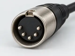
Compare look-alikes: Five-pin DIN versus five-pin XLR

Candidate selection does not confirm the identity or capabilities of your physical item.

SOURCE-OBSERVED AUDIO COMPONENTS

A DIN outline does not establish MIDI.

NYS322 is a male cable component. Its key and five-position arc are physical cues, not a MIDI port direction or a complete cable specification.

5-pole DIN / NYS322. Source-facing end view / key above contacts. Five positions across the lower arc; Upper key; no contact numbering; The part source does not establish MIDI service. Original qualitative study, not a pinout.
REAN NYS322 / product-linked drawing
Male DIN cable component · Source, orientation and omissions (private workspace)
Read the evidence and its limits
  1. REAN identifies NYS322 as a male five-pole DIN cable component; its linked end view places the five contacts in a lower arc below the key. C110C

    Named component identity and observed end view only. This does not establish MIDI service, IN/OUT direction or a completed MIDI cable.

    S617 · REAN ↗ · S618 · REAN ↗

  2. The MIDI Association separately specifies a MIDI transport using five-pin DIN. C110B

    Identification and explicitly scoped documentation only; not an end-to-end connection approval

    S090 · MIDI Association ↗

Compare the five audio and music references →

Evidence behind this page

Scope first. Source second. Approval separate.

4 linked sources · 3 scoped claims · 0 sources with inspection/access flags.

Page scope: consumer_reference_expansion

Assessment 2026-10-22 · earliest scheduled source review 2027-01-01. This is a recorded-date assessment, not a live source check. Page-level independent review is not established by this panel.

Inspect 4 source scopes, access limits and dates

S089 · DIN and Mini-DIN identification guide

C2G / Legrand · Manufacturer / product-owner domain · inspected 2026-10-03 · due 2027-01-01

Within inspection window

Scoped support: Distinct DIN / Mini-DIN arrangements and the S-Video and PS/2 examples.

Not established / limitations: A historical application is not a guarantee of what a particular port carries.

Locator: 5-pin DIN; 4-pin Mini DIN; 6-pin Mini DIN

S090 · MIDI transports — DIN and TRS

MIDI Association · Standards-organization domain · inspected 2026-10-03 · due 2027-01-01

Within inspection window

Scoped support: MIDI has 5-pin DIN and separately specified TRS transports.

Not established / limitations: No pinout or adapter wiring is reproduced; this overview does not establish a given device wiring type.

Locator: 5 PIN DIN ELECTRICAL SPECS; SPECIFICATION FOR USE OF TRS CONNECTORS WITH MIDI DEVICES

S617 · REAN NYS322 male five-pole DIN cable connector

REAN · Unclassified publisher domain · inspected 2026-10-13 · due 2027-01-11

Within inspection window

Scoped support: Exact NYS322 component identity; not a MIDI cable, device role or transport approval.

Not established / limitations: Exact NYS322 component identity; not a MIDI cable, device role or transport approval. Raw document bytes were not obtained in the container; no raw-file hash or archived-source possession is claimed.

Locator: Product description; gender; article variations; linked NYS322 drawing.

S618 · NYS322 component drawing

REAN · Unclassified publisher domain · inspected 2026-10-13 · due 2027-01-11

Within inspection window

Scoped support: Product-linked male DIN component; no source dimensions, pin numbers or circuit copied.

Not established / limitations: Product-linked male DIN component; no source dimensions, pin numbers or circuit copied. Raw document bytes were not obtained in the container; no raw-file hash or archived-source possession is claimed.

Locator: Single sheet; side and end views. Designer/checked date 2020.11.11. Five lower-arc contact positions and upper key visually inspected.

Trace 3 claims to their source records

C110A · P110

The DIN guide describes a five-pin circular connector used by older AT-style keyboards.

Claim scope: Identification and explicitly scoped documentation only; not an end-to-end connection approval

Source links: S089 · Evidence trail → (private workspace)

C110B · P110

The MIDI Association separately specifies a MIDI transport using five-pin DIN.

Claim scope: Identification and explicitly scoped documentation only; not an end-to-end connection approval

Source links: S090 · Evidence trail → (private workspace)

C110C · P110

REAN identifies NYS322 as a male five-pole DIN cable component; its linked end view places the five contacts in a lower arc below the key.

Claim scope: Named component identity and observed end view only. This does not establish MIDI service, IN/OUT direction or a completed MIDI cable.

Source links: S617 · S618 · Evidence trail → (private workspace)

Prepare this page for review → (private workspace)Read the evidence method →

Recorded evidence only. An inspection date, publisher label, source link or generated packet is not independent technical review, hardware testing, fabrication approval or a compatibility verdict.