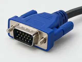
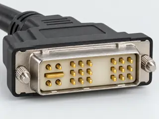
FIELD GUIDESource-led reference

P117 / Video / Connector

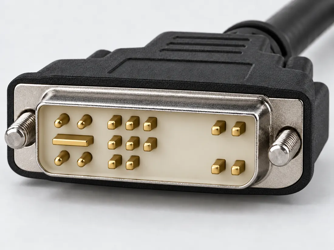
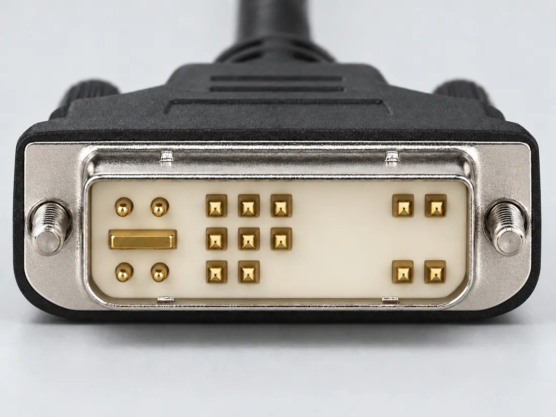
DVI-A connector

DVI-A is the analog-only member of the DVI family, not another name for a digital DVI link.

Also called DVI analog DVI-A 17 pin 12+5 DVI

A DVI-shaped plug does not promise digital video.

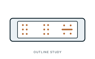
Look for

Read the DVI-A label and compare the documented arrangement. Do not infer signal conversion from a mechanical adapter.

Claim inspection dates: 2026-10-03, 2026-10-22 · Independent review pending

The useful distinction

Recognize it. Then verify it.

DVI-A is the analog-only member of the DVI family, not another name for a digital DVI link. [C117A]

DVI-D is a digital-only type, while DVI-I has a different integrated role. [C117B]

Goobay 69971 DVI-A male to VGA female adapter, listedDVI-side continuity: exact numbered manufacturer contact normalization. Device-specific source-backed research only; see per-contact source and scope. [C884A]

Source-scoped identification facts

Each value retains its exact example, role and measurement axis. Facts from different parts must not be combined into an invented component.

Documented examples; not a mating drawing or compatibility approval
Nominal contacts17S093Source naming counts the blade in the 17-pin total; compare the manufacturer layout.
Connector roleplug (DVIVGAMM1M)S934Named source examples retain separate role, part, view and axis limits; values are not a universal family specification. DVIVGAMM1M. Documented role: plug. Productwidth41mm andheight15mm describe the cable assembly without endpoint-specific axes,so they are not counted as connector dimensions.; No active digital-to-analog conversion. Nickel plating in table and gold-contact wording in features retained as different surfaces without forcing a single finish.
Coupling / latchMoulded cable ends with strain relief; exact DVI-A male to VGA male assembly (DVIVGAMM1M)S934Named source examples retain separate role, part, view and axis limits; values are not a universal family specification. DVIVGAMM1M. Documented role: plug. Productwidth41mm andheight15mm describe the cable assembly without endpoint-specific axes,so they are not counted as connector dimensions.; No active digital-to-analog conversion. Nickel plating in table and gold-contact wording in features retained as different surfaces without forcing a single finish.
ManufacturerStarTech.com (DVIVGAMM1M)S934Named source examples retain separate role, part, view and axis limits; values are not a universal family specification. DVIVGAMM1M. Documented role: plug. Productwidth41mm andheight15mm describe the cable assembly without endpoint-specific axes,so they are not counted as connector dimensions.; No active digital-to-analog conversion. Nickel plating in table and gold-contact wording in features retained as different surfaces without forcing a single finish.
SeriesDVI-A to VGA cable (DVIVGAMM1M)S934Named source examples retain separate role, part, view and axis limits; values are not a universal family specification. DVIVGAMM1M. Documented role: plug. Productwidth41mm andheight15mm describe the cable assembly without endpoint-specific axes,so they are not counted as connector dimensions.; No active digital-to-analog conversion. Nickel plating in table and gold-contact wording in features retained as different surfaces without forcing a single finish.
Exact part / implementationDVIVGAMM1M (DVIVGAMM1M)S934Named source examples retain separate role, part, view and axis limits; values are not a universal family specification. DVIVGAMM1M. Documented role: plug. Productwidth41mm andheight15mm describe the cable assembly without endpoint-specific axes,so they are not counted as connector dimensions.; No active digital-to-analog conversion. Nickel plating in table and gold-contact wording in features retained as different surfaces without forcing a single finish.

Not recorded: Positions / cavity span, Populated contacts, Contact rows, Contact pitch, Dimensions / axis, Contact gender / arrangement, Mounting, Keying / polarization, Shell / form, Recorded markings, View convention. Unknown fields stay unknown; illustrations supply no measurements or pin assignments.

Recorded variant and source limits
  • Check the exact device manual before wiring or applying power.
  • DVI 1.0 analog signal assignments (Table 5-2 contacts used by the analog interface): Plug face per Figure 5-6 (pin 1 upper right).
  • Hatteland Technology DVI-4 DVI (12+5) male to HD15 female adapter (device-specific): Male DVI face per the manufacturer drawing.
  • Analog signal assignments of the DDWG combined connector, as used by a DVI-A plug: Plug face per DDWG Fig. 5-6; numbering by contact number.
Report a correction to these facts →

Bounded facts, visible unknowns

Specifications and limits

DVI-A connector facts and limitations
Documented identificationStarTech lists DVI-A as a 17-pin analog-only form. [C117A]
Important distinctionDVI-D is a digital-only type, while DVI-I has a different integrated role. [C117B]
Mechanical dimensionsNo independently approved mechanical dimensions. Do not use this record for fabrication or fit testing.
Engineering pinoutSource-checked engineering profile available; independent review pending. Open engineering profile →
Verified device listNot included. Check exact device and accessory documentation.
A boundary, not an omission to guess around.

Record the exact device model and the label beside the port. Obtain its manual and the accessory documentation. Keep unknown properties unknown instead of filling them from a visually similar item.

Before you connect

What to check

  1. Read the signal type of the source.
  2. Read the signal type of the destination.
  3. Distinguish conversion electronics from a connector-shape adapter.
Trace a supported connection class →

Pins & wiring

Pinout

Choose the exact wiring. Pin numbers follow its stated view; a schematic does not establish physical positions. Check your exact device before wiring.

What the status labels mean
Confirmed
Recorded research passes agree within this variant; this is not independent human review or hardware validation.
Single source
Only one underlying document, or one pass, supports this assignment.
Device-specific
Supported for the named equipment or wiring only. Check your device’s manual.
Unverified
Missing or conflicting evidence. Do not wire from this row.
Not connected
The source explicitly says NC, no contact or no pin for this wiring.
Wiring variant

DVI 1.0 analog signal assignments (Table 5-2 contacts used by the analog interface)

View and evidence limits

Plug face per Figure 5-6 (pin 1 upper right).

  • P117 DVI-A — **Agree** on the analog contacts (C1–C5, 8 V-sync, 15 ground) — DVI 1.0 has no DVI-A table, so neither pass could establish which numbered contacts a DVI-A plug actually populates. Pins 6, 7, 14 and 16 are unverified in B. A's Hatteland DVI-4 adapter ties pin 16 to +5 V, which conflicts with the spec's Hot Plug Detect, and leaves pin 20 unlisted. **Publish only the analog contacts as confirmed.**
  • DVI 1.0 has no 'DVI-A' connector table. Figure 5-6 draws the analog plug with the full 24-position array plus C1-C5, so which digital-field contacts a DVI-A plug actually carries is not established by the specification.
  • Neither DVI 1.0 nor a connector maker's DVI-A drawing establishing which digital-field positions (6, 7, 14, 16 and the 12-position count) a DVI-A plug carries was found.
  • Pin 20 is not listed anywhere in the DVI-4 table. The table names 6 digital-field contacts (6, 7, 8, 14, 15, 16) although the product is described as 12+5.
  • DVI 1.0 assigns DDC Clock, DDC Data, +5V and Hot Plug Detect to these pins on the combined connector, but does not state that an analog-only plug carries them.
DVI-A engineering referencePlug face per Figure 5-6 (pin 1 upper right).SCHEMATIC · physical positions unconfirmedNot to scale · check the named wiring and device manualC1: Analog Red (single_source)C1C2: Analog Green (single_source)C2C3: Analog Blue (single_source)C3C4: Analog Horizontal Sync (single_source)C4C5: Analog Ground (single_source)C58: Analog Vertical Sync (single_source)815: Ground (return for +5V, HSync, and VSync) (single_source)15powergrounddataConfigshieldNCUnknown
Schematic only · physical contact positions unconfirmed. Original drawing · not to scale. Scroll sideways if needed.
DVI 1.0 analog signal assignments (Table 5-2 contacts used by the analog interface) — source-scoped contact map
PinSignalWhat it doesStatus
C1Analog RedControl, detection or configuration connection; check the source and device.Single source
Sources
C2Analog GreenWire colour for this termination: Analog Green.Single source
Sources
C3Analog BlueWire colour for this termination: Analog Blue.Single source
Sources
C4Analog Horizontal SyncControl, detection or configuration connection; check the source and device.Single source
Sources
C5Analog GroundControl, detection or configuration connection; check the source and device.Single source
Sources
8Analog Vertical SyncControl, detection or configuration connection; check the source and device.Single source
Sources
15Ground (return for +5V, HSync, and VSync)Ground reference and return.Single source
Sources
Sources (1)

Hatteland Technology DVI-4 DVI (12+5) male to HD15 female adapter (device-specific)

Device-specific wiring. Check your device’s manual before connecting or applying power.

View and evidence limits

Male DVI face per the manufacturer drawing.

  • P117 DVI-A — **Agree** on the analog contacts (C1–C5, 8 V-sync, 15 ground) — DVI 1.0 has no DVI-A table, so neither pass could establish which numbered contacts a DVI-A plug actually populates. Pins 6, 7, 14 and 16 are unverified in B. A's Hatteland DVI-4 adapter ties pin 16 to +5 V, which conflicts with the spec's Hot Plug Detect, and leaves pin 20 unlisted. **Publish only the analog contacts as confirmed.**
  • Device-specific: the vendor calls it 'DVI-I (12+5) Single Link Male'; the 12+5 analog-style contact set is used here as named-device evidence for a DVI-A plug.
  • The research contains rows outside its declared pin set; those extra rows are withheld.
  • Neither DVI 1.0 nor a connector maker's DVI-A drawing establishing which digital-field positions (6, 7, 14, 16 and the 12-position count) a DVI-A plug carries was found.
  • Pin 20 is not listed anywhere in the DVI-4 table. The table names 6 digital-field contacts (6, 7, 8, 14, 15, 16) although the product is described as 12+5.
  • DVI 1.0 assigns DDC Clock, DDC Data, +5V and Hot Plug Detect to these pins on the combined connector, but does not state that an analog-only plug carries them.
DVI-A engineering referenceMale DVI face per the manufacturer drawing.SCHEMATIC · physical positions unconfirmedNot to scale · check the named wiring and device manualC1: Analog Red (device_specific)C1C2: Analog Green (device_specific)C2C3: Analog Blue (device_specific)C3C4: Analog Horizontal Sync. (device_specific)C4C5: Analog Ground (return for R, G, B signals) (device_specific)C56: Not confirmed (unverified)67: Not confirmed (unverified)78: Analog Vertical Sync. (device_specific)814: Not confirmed (unverified)1415: Digital Ground (for +5V and analog sync.) (device_specific)1516: Not confirmed (unverified)16Shield: Not confirmed (unverified)ShieldpowergrounddataConfigshieldNCUnknown
Schematic only · physical contact positions unconfirmed. Original drawing · not to scale. Scroll sideways if needed.
Hatteland Technology DVI-4 DVI (12+5) male to HD15 female adapter (device-specific) — source-scoped contact map
PinSignalWhat it doesStatus
C1Analog RedControl, detection or configuration connection; check the source and device.Device-specific
Sources
C2Analog GreenWire colour for this termination: Analog Green.Device-specific
Sources
C3Analog BlueWire colour for this termination: Analog Blue.Device-specific
Sources
C4Analog Horizontal Sync.Control, detection or configuration connection; check the source and device.Device-specific
Sources
C5Analog Ground (return for R, G, B signals)Control, detection or configuration connection; check the source and device.Device-specific
Sources
6Not confirmedNo settled assignment. Do not wire from this row.Unverified
Sources
7Not confirmedNo settled assignment. Do not wire from this row.Unverified
Sources
8Analog Vertical Sync.Control, detection or configuration connection; check the source and device.Device-specific
Sources
14Not confirmedNo settled assignment. Do not wire from this row.Unverified
Sources
15Digital Ground (for +5V and analog sync.)Power connection (Digital Ground (for +5V and analog sync.)). Check the specified supply.Device-specific
Sources
16Not confirmedNo settled assignment. Do not wire from this row.Unverified
Sources
ShieldNot confirmedNo settled assignment. Do not wire from this row.Unverified
Sources
Sources (1)

Analog signal assignments of the DDWG combined connector, as used by a DVI-A plug

View and evidence limits

Plug face per DDWG Fig. 5-6; numbering by contact number.

  • P117 DVI-A — **Agree** on the analog contacts (C1–C5, 8 V-sync, 15 ground) — DVI 1.0 has no DVI-A table, so neither pass could establish which numbered contacts a DVI-A plug actually populates. Pins 6, 7, 14 and 16 are unverified in B. A's Hatteland DVI-4 adapter ties pin 16 to +5 V, which conflicts with the spec's Hot Plug Detect, and leaves pin 20 unlisted. **Publish only the analog contacts as confirmed.**
  • DVI 1.0 does not use the name 'DVI-A'. It defines an 'analog plug' that mates with the combined receptacle.
  • No manufacturer drawing was retrieved: the Molex 74323-series DVI-A plug drawings timed out, and a Lindy DVI-A cable datasheet gives no pinout. TMDS positions 1-5, 9-13 and 17-24 are not recorded for DVI-A.
  • Pins 6, 7, 14, 15 and 16 are assigned on the combined connector, but no source here shows them present on a DVI-A plug.
DVI-A engineering referencePlug face per DDWG Fig. 5-6; numbering by contact number.SCHEMATIC · physical positions unconfirmedNot to scale · check the named wiring and device manual6: Not confirmed (unverified)67: Not confirmed (unverified)78: Analog Vertical Sync (single_source)814: Not confirmed (unverified)1415: Not confirmed (unverified)1516: Not confirmed (unverified)16C1: Analog Red (single_source)C1C2: Analog Green (single_source)C2C3: Analog Blue (single_source)C3C4: Analog Horizontal Sync (single_source)C4C5: Analog Ground (single_source)C5powergrounddataConfigshieldNCUnknown
Schematic only · physical contact positions unconfirmed. Original drawing · not to scale. Scroll sideways if needed.
Analog signal assignments of the DDWG combined connector, as used by a DVI-A plug — source-scoped contact map
PinSignalWhat it doesStatus
6Not confirmedNo settled assignment. Do not wire from this row.Unverified
Sources
7Not confirmedNo settled assignment. Do not wire from this row.Unverified
Sources
8Analog Vertical SyncControl, detection or configuration connection; check the source and device.Single source
Sources
14Not confirmedNo settled assignment. Do not wire from this row.Unverified
Sources
15Not confirmedNo settled assignment. Do not wire from this row.Unverified
Sources
16Not confirmedNo settled assignment. Do not wire from this row.Unverified
Sources
C1Analog RedControl, detection or configuration connection; check the source and device.Single source
Sources
C2Analog GreenWire colour for this termination: Analog Green.Single source
Sources
C3Analog BlueWire colour for this termination: Analog Blue.Single source
Sources
C4Analog Horizontal SyncControl, detection or configuration connection; check the source and device.Single source
Sources
C5Analog GroundControl, detection or configuration connection; check the source and device.Single source
Sources
Sources (1)

Goobay 69971 DVI-A male to VGA female adapter, listedDVI-side continuity

Device-specific wiring. Check your device’s manual before connecting or applying power.

View and evidence limits

Manufacturer sheet 1 numbered DVI plug outline and Pin Out wiring table. Only explicit DVI contact designators are normalized. No wire-entry/termination mirror or inferred contact population is asserted.

  • This is an11-listed-contact partial continuity map, not a17-contact population inventory. Manufacturer advertises12+5 but does not identify all remaining positions as wired,NC or absent.
  • SHIELD-to-SHIELD is separately explicit evidence but not counted as a numbered mating contact or a28th new assignment.
  • Do not generalize this adapter continuity, especially14/16 grouping, to generic DVI-A or the different Hatteland adapter. No voltage/current/feature capability inferred.
  • Schematic listing only, not to scale; fabrication remains unapproved.
DVI-A engineering referenceManufacturer sheet 1 numbered DVI plug outline and Pin Out wiring table. Only explicit DVI contact designators are normalized. No wire-entry/termination mirror or inferred contact population is asserted.SCHEMATIC · physical positions unconfirmedNot to scale · check the named wiring and device manualC1: VGA 1 (device_specific)C1C2: VGA 2 (device_specific)C2C3: VGA 3 (device_specific)C3C4: VGA 13 (device_specific)C4C5: VGA 6,7,8 (device_specific)C58: VGA 14 (device_specific)87: VGA 12 (device_specific)76: VGA 15 (device_specific)614: VGA 9 (device_specific)1416: VGA 9 (device_specific)1615: VGA 10,5 (device_specific)15powergrounddataConfigshieldNCUnknown
Schematic only · physical contact positions unconfirmed. Original drawing · not to scale. Scroll sideways if needed.
Goobay 69971 DVI-A male to VGA female adapter, listedDVI-side continuity — source-scoped contact map
PinSignalWhat it doesStatus
C1VGA 1Connected to VGA contact1 on the named 69971 adapter.Device-specific
Sources
C2VGA 2Connected to VGA contact2 on the named 69971 adapter.Device-specific
Sources
C3VGA 3Connected to VGA contact3 on the named 69971 adapter.Device-specific
Sources
C4VGA 13Connected to VGA contact13 on the named 69971 adapter.Device-specific
Sources
C5VGA 6,7,8Connected to VGA contacts6,7,8 on the named 69971 adapter.Device-specific
Sources
8VGA 14Connected to VGA contact14 on the named 69971 adapter.Device-specific
Sources
7VGA 12Connected to VGA contact12 on the named 69971 adapter.Device-specific
Sources
6VGA 15Connected to VGA contact15 on the named 69971 adapter.Device-specific
Sources
14VGA 9Manufacturer groupsDVI 14 and16 as connected to VGA 9. No independent voltage/polarity or HPD function is asserted.Device-specific
Sources
16VGA 9Manufacturer groupsDVI 14 and16 as connected to VGA 9. No independent voltage/polarity or HPD function is asserted.Device-specific
Sources
15VGA 10,5Connected to VGA contacts10,5 on the named 69971 adapter.Device-specific
Sources
Sources (1)

What is not established

This field note does not approve a connection, publish a pinout or provide a measured template. Use the linked source scope and the checklist as a documentation starting point.

Your next step

Move from the form to the requirement.

The source trail

Evidence for this page

AI-assisted inspection is not independent engineering review. Source scope and access limitations are disclosed below. Procedural checklists are editorial requirements, not hardware measurements.

Back to first citation ↑
C117ASource checked · pending review

StarTech lists DVI-A as a 17-pin analog-only form.

StarTech.com · DVI identification FAQ in DVIVGAMF documentation ↗

Locator: How can I identify which DVI connector type I have or need?
Access: public page. The adapter-specific product claims and typical resolution examples are not generalized to all DVI equipment.

S093: full source recordInspect review dependencies → (private workspace)

Claim scope: Identification and explicitly scoped documentation only; not an end-to-end connection approval. Next review due 2027-01-01.

Back to first citation ↑
C117BSource checked · pending review

DVI-D is a digital-only type, while DVI-I has a different integrated role.

StarTech.com · DVI identification FAQ in DVIVGAMF documentation ↗

Locator: How can I identify which DVI connector type I have or need?
Access: public page. The adapter-specific product claims and typical resolution examples are not generalized to all DVI equipment.

S093: full source recordInspect review dependencies → (private workspace)

Claim scope: Identification and explicitly scoped documentation only; not an end-to-end connection approval. Next review due 2027-01-01.

Back to first citation ↑
C884ASource checked · pending review

Goobay 69971 DVI-A male to VGA female adapter, listedDVI-side continuity: exact numbered manufacturer contact normalization. Device-specific source-backed research only; see per-contact source and scope.

Wentronic GmbH / Goobay · Goobay 69971 DVI-A/VGA Monitor Adapter product drawing ↗

Locator: Sheet 1, upper-left Pinbelegung/Pin Out DVI→VGA wiring table; upper-middle numberedDVI outline; lower title block
Access: public pdf text. Eleven numberedDVI designators plus SHIELD are mapped; remaining advertised 12+5 positions are not established as wired/NC/absent. No generic DVI-A population, voltage, power capability, video capability or physical contact geometry inferred.

S884: full source recordInspect review dependencies → (private workspace)

Claim scope: Only the named implementation and explicit numbered rows; no universal family claim, independent confirmation, hardware verification or fabrication approval.. Next review due 2027-01-20.

Suggest a correction to this field note →

Put this field note to work.

Add to discovery trayRecord an unsaved candidate (private workspace)

Compare look-alikes: DVI-A, DVI-I single-link and DVI-D

Candidate selection does not confirm the identity or capabilities of your physical item.

Evidence behind this page

Scope first. Source second. Approval separate.

2 linked sources · 3 scoped claims · 0 sources with inspection/access flags.

Page scope: consumer_reference_expansion

Assessment 2026-10-22 · earliest scheduled source review 2027-01-01. This is a recorded-date assessment, not a live source check. Page-level independent review is not established by this panel.

Inspect 2 source scopes, access limits and dates

S093 · DVI identification FAQ in DVIVGAMF documentation

StarTech.com · Manufacturer / product-owner domain · inspected 2026-10-03 · due 2027-01-01

Within inspection window

Scoped support: DVI-I single-link is listed as 23-pin; DVI-A as 17-pin; digital/analog roles differ.

Not established / limitations: The adapter-specific product claims and typical resolution examples are not generalized to all DVI equipment.

Locator: How can I identify which DVI connector type I have or need?

S884 · Goobay 69971 DVI-A/VGA Monitor Adapter product drawing

Wentronic GmbH / Goobay · Unclassified publisher domain · inspected 2026-10-22 · due 2027-01-20

Within inspection window

Scoped support: Only explicitly listed continuity mappings of named 69971 DVI-A male12+5 to VGA female15 adapter.

Not established / limitations: Eleven numberedDVI designators plus SHIELD are mapped; remaining advertised 12+5 positions are not established as wired/NC/absent. No generic DVI-A population, voltage, power capability, video capability or physical contact geometry inferred.

Locator: Sheet 1, upper-left Pinbelegung/Pin Out DVI→VGA wiring table; upper-middle numberedDVI outline; lower title block

Trace 3 claims to their source records

C117A · P117

StarTech lists DVI-A as a 17-pin analog-only form.

Claim scope: Identification and explicitly scoped documentation only; not an end-to-end connection approval

Source links: S093 · Evidence trail → (private workspace)

C117B · P117

DVI-D is a digital-only type, while DVI-I has a different integrated role.

Claim scope: Identification and explicitly scoped documentation only; not an end-to-end connection approval

Source links: S093 · Evidence trail → (private workspace)

C884A · P117

Goobay 69971 DVI-A male to VGA female adapter, listedDVI-side continuity: exact numbered manufacturer contact normalization. Device-specific source-backed research only; see per-contact source and scope.

Claim scope: Only the named implementation and explicit numbered rows; no universal family claim, independent confirmation, hardware verification or fabrication approval.

Source links: S884 · Evidence trail → (private workspace)

Prepare this page for review → (private workspace)Read the evidence method →

Recorded evidence only. An inspection date, publisher label, source link or generated packet is not independent technical review, hardware testing, fabrication approval or a compatibility verdict.