FIELD GUIDESource-led reference

P264 / USB / Connector

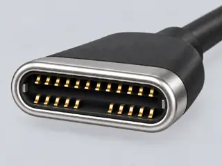
USB 3.1 front-panel Key-A 20-pin header

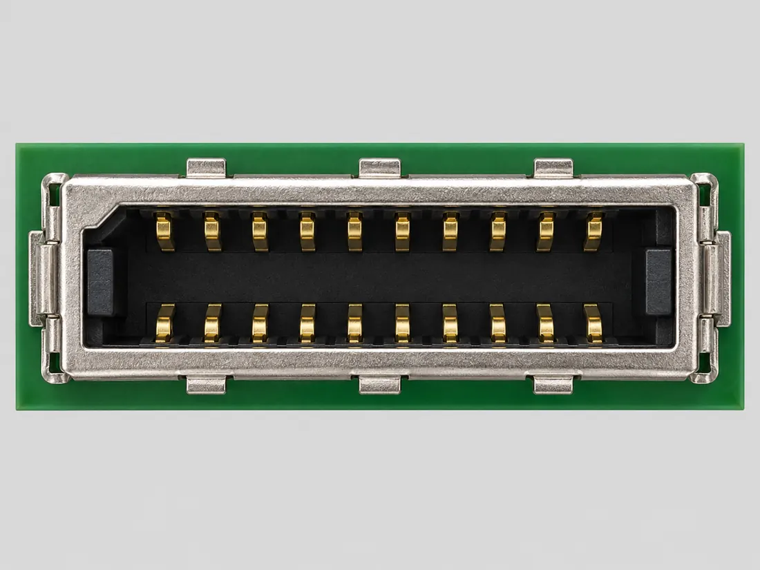
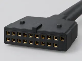
The USB-IF front-panel internal-cable specification defines a 20-pin Key-A header that can support one USB Type-C port or one Standard-A port.

Also called USB Key-A header USB 3.1 front panel header 20-pin Key-A Type-C front panel header

Key-A is a specific internal mating interface and must not be conflated with the older 19-pin USB 3.0 front-panel header or with external USB Type-A/Type-C connectors.

Look for

Verify the Key-A housing/keying and motherboard documentation before choosing a front-panel cable; do not infer USB mode or charging capability from the header alone.

Claim inspection dates: 2026-10-06 · Independent review pending

The useful distinction

Recognize it. Then verify it.

The USB-IF front-panel internal-cable specification defines a 20-pin Key-A header that can support one USB Type-C port or one Standard-A port. [C264A]

Source-scoped identification facts

Each value retains its exact example, role and measurement axis. Facts from different parts must not be combined into an invented component.

Documented examples; not a mating drawing or compatibility approval
Nominal contacts20S284Source-backed nominal position/contact count: 20.
Contact rows2S829Named source examples retain separate role, part, view and axis limits; values are not a universal family specification. USB-IF2017 KeyA20pin shielded header reference. Documented role: socket. 13mm is shielded reference header span,not every vendor part. No manufacturer/part invented.; 19mm mated assembly and right-angle overmould reference maxima are excluded from bare header geometry.; USB-IFPDFmetadata inaccurately labelsPCMCIAProposal279;actualtitle/content checked asUSB3.1frontpanelRev1.1.; Required arrow is documented reference design scope,not an observed individual specimen.
Contact pitch0.8 mm row-longitudinal mating contact centerlineS829Named source examples retain separate role, part, view and axis limits; values are not a universal family specification. USB-IF2017 KeyA20pin shielded header reference. Documented role: socket. 13mm is shielded reference header span,not every vendor part. No manufacturer/part invented.; 19mm mated assembly and right-angle overmould reference maxima are excluded from bare header geometry.; USB-IFPDFmetadata inaccurately labelsPCMCIAProposal279;actualtitle/content checked asUSB3.1frontpanelRev1.1.; Required arrow is documented reference design scope,not an observed individual specimen.
Dimensions / axis13 ± 0.25 mm header shell horizontal span in front drawingS829Named source examples retain separate role, part, view and axis limits; values are not a universal family specification. USB-IF2017 KeyA20pin shielded header reference. Documented role: socket. 13mm is shielded reference header span,not every vendor part. No manufacturer/part invented.; 19mm mated assembly and right-angle overmould reference maxima are excluded from bare header geometry.; USB-IFPDFmetadata inaccurately labelsPCMCIAProposal279;actualtitle/content checked asUSB3.1frontpanelRev1.1.; Required arrow is documented reference design scope,not an observed individual specimen.
Connector roleheader; socketS284 · S293 · S829Named source examples retain separate role, part, view and axis limits; values are not a universal family specification. USB-IF Key-A motherboard front-panel internal header USB-IF2017 KeyA20pin shielded header reference. Documented role: socket. 13mm is shielded reference header span,not every vendor part. No manufacturer/part invented.; 19mm mated assembly and right-angle overmould reference maxima are excluded from bare header geometry.; USB-IFPDFmetadata inaccurately labelsPCMCIAProposal279;actualtitle/content checked asUSB3.1frontpanelRev1.1.; Required arrow is documented reference design scope,not an observed individual specimen.
Keying / polarizationKeyAplug mates only corresponding KeyAheader;KeyB is distinct;internal cable not reversible.S829Named source examples retain separate role, part, view and axis limits; values are not a universal family specification. USB-IF2017 KeyA20pin shielded header reference. Documented role: socket. 13mm is shielded reference header span,not every vendor part. No manufacturer/part invented.; 19mm mated assembly and right-angle overmould reference maxima are excluded from bare header geometry.; USB-IFPDFmetadata inaccurately labelsPCMCIAProposal279;actualtitle/content checked asUSB3.1frontpanelRev1.1.; Required arrow is documented reference design scope,not an observed individual specimen.
SeriesUSB-IF2017 KeyA20pin shielded header referenceS829Named source examples retain separate role, part, view and axis limits; values are not a universal family specification. USB-IF2017 KeyA20pin shielded header reference. Documented role: socket. 13mm is shielded reference header span,not every vendor part. No manufacturer/part invented.; 19mm mated assembly and right-angle overmould reference maxima are excluded from bare header geometry.; USB-IFPDFmetadata inaccurately labelsPCMCIAProposal279;actualtitle/content checked asUSB3.1frontpanelRev1.1.; Required arrow is documented reference design scope,not an observed individual specimen.
Recorded markingsOrientation arrow required on header and plug along length direction near pin3 per sec2.3item1.S829Named source examples retain separate role, part, view and axis limits; values are not a universal family specification. USB-IF2017 KeyA20pin shielded header reference. Documented role: socket. 13mm is shielded reference header span,not every vendor part. No manufacturer/part invented.; 19mm mated assembly and right-angle overmould reference maxima are excluded from bare header geometry.; USB-IFPDFmetadata inaccurately labelsPCMCIAProposal279;actualtitle/content checked asUSB3.1frontpanelRev1.1.; Required arrow is documented reference design scope,not an observed individual specimen.
View conventionContact assignment is published looking into the front of the header: P1–P10 across the upper row and P20–P11 across the lower row in the USB-IF Figure 3-1 view.; Fig2-1dimensioned front header mating face;Fig3-1explicitly looks into front of header;plug interface separateFig2-5.S284 · S293 · S829Named source examples retain separate role, part, view and axis limits; values are not a universal family specification. Existing engineering orientation text; source/part/view remains controlling. USB-IF2017 KeyA20pin shielded header reference. Documented role: socket. 13mm is shielded reference header span,not every vendor part. No manufacturer/part invented.; 19mm mated assembly and right-angle overmould reference maxima are excluded from bare header geometry.; USB-IFPDFmetadata inaccurately labelsPCMCIAProposal279;actualtitle/content checked asUSB3.1frontpanelRev1.1.; Required arrow is documented reference design scope,not an observed individual specimen.

Not recorded: Positions / cavity span, Populated contacts, Contact gender / arrangement, Mounting, Coupling / latch, Shell / form, Manufacturer, Exact part / implementation. Unknown fields stay unknown; illustrations supply no measurements or pin assignments.

Recorded variant and source limits
  • This Key-A contact assignment is the USB-IF one-Type-C-port reference design; it does not prove that a specific motherboard implements every USB mode, Alternate Mode or charging feature.
  • Reference mechanical dimensions remain in the linked specification and are not republished as fabrication approval.
  • The internal interface is not reversible/flip-able even though an external USB Type-C plug is reversible.
  • Key-A 20-pin header/plug wired to one USB Type-C port: Front of header, per Figure 3-1.
  • Key-A 20-pin header/plug wired to one Standard-A port (subset): Front of header, per Figure 3-2.
  • Key-A 20-pin header, one USB Type-C front port (USB-IF reference): Looking into the front of the header (Figure 3-1).
  • Key-A 20-pin header/plug wired to one Standard-A front port (USB-IF reference): Looking into the front of the header (Figure 3-2).
Report a correction to these facts →

Bounded facts, visible unknowns

Specifications and limits

USB 3.1 front-panel Key-A 20-pin header facts and limitations
Documented identification20-position/contact recognition fact in the cited implementation. [C264A]
Mechanical dimensionsNo independently reviewed mechanical drawing in V43; do not use this page for fabrication, fit testing or tolerance work.
Engineering pinoutSource-checked engineering profile available; independent review pending. Open engineering profile →
Verified device listNot included. Check exact device and accessory documentation.
A boundary, not an omission to guess around.

Use the source-backed form or position count only for identification. Resolve ratings, protocol, direction, wiring, cable construction and exact device support from the relevant equipment and component documentation.

Before you connect

What to check

  1. Identify the exact connector family and variant from the equipment or cable documentation.
  2. Keep shape, contact count, protocol, electrical rating and device support as separate facts.
  3. Do not force, rewire or adapt a connector from this recognition record; resolve the remaining requirements first.
Trace a supported connection class →

Pins & wiring

Pinout

Choose the exact wiring. Pin numbers follow its stated view; a schematic does not establish physical positions. Check your exact device before wiring.

What the status labels mean
Confirmed
Recorded research passes agree within this variant; this is not independent human review or hardware validation.
Single source
Only one underlying document, or one pass, supports this assignment.
Device-specific
Supported for the named equipment or wiring only. Check your device’s manual.
Unverified
Missing or conflicting evidence. Do not wire from this row.
Not connected
The source explicitly says NC, no contact or no pin for this wiring.
Wiring variant

Key-A 20-pin header/plug wired to one USB Type-C port

View and evidence limits

Front of header, per Figure 3-1.

  • P264 USB 3.1 Key-A 20-pin header — **Agree** on all 20 pins for both the Type-C and Standard-A front-panel variants, including the 7 unused pins in the Standard-A wiring — USB-IF front-panel document, Tables 3-3 and 3-4. Pass B noted an apparent typo in the pin 5 wire label in Table 3-4.
  • Rx/Tx defined from host perspective.
  • Pins B6/B7 at the Type-C receptacle are shorted to A6/A7 on the paddle card (Table 3-3 note 3).
  • Section 2.1 reference drawings (Figures 2-1/2-2, PDF pp.6-7) were not dimensionally transcribed; key location relative to P1 is not recorded here.
  • Defined in the same document (Section 3.2.2 onward) but outside P264 scope; not transcribed.
  • No motherboard manual consulted; vendor silkscreen names may differ from the USB-IF names.
USB front-panel Key-A 20-pin Type-C assignmentFront of header, per Figure 3-1.SCHEMATIC · physical positions unconfirmedNot to scale · check the named wiring and device manualP1: VBUS (single_source)P1P2: TX1+ (SSTXp1) (single_source)P2P3: TX1- (SSTXn1) (single_source)P3P4: GND (single_source)P4P5: RX1+ (SSRXp1) (single_source)P5P6: RX1- (SSRXn1) (single_source)P6P7: VBUS (single_source)P7P8: CC1 (single_source)P8P9: SBU1 (single_source)P9P10: SBU2 (single_source)P10P11: VBUS (single_source)P11P12: TX2+ (SSTXp2) (single_source)P12P13: TX2- (SSTXn2) (single_source)P13P14: GND (single_source)P14P15: RX2+ (SSRXp2) (single_source)P15P16: RX2- (SSRXn2) (single_source)P16P17: GND (single_source)P17P18: D- (Dn) (single_source)P18P19: D+ (Dp) (single_source)P19P20: CC2 (single_source)P20Shell: Shield (single_source)ShellpowergrounddataConfigshieldNCUnknown
Schematic only · physical contact positions unconfirmed. Original drawing · not to scale. Scroll sideways if needed.
Key-A 20-pin header/plug wired to one USB Type-C port — source-scoped contact map
PinSignalWhat it doesStatus
P1VBUSUSB bus power; voltage and current depend on the device.Single source
Sources
P2TX1+ (SSTXp1)Signal conductor. Pair, polarity and direction follow this named wiring.Single source
Sources
P3TX1- (SSTXn1)Signal conductor. Pair, polarity and direction follow this named wiring.Single source
Sources
P4GNDGround reference and return.Single source
Sources
P5RX1+ (SSRXp1)Signal conductor. Pair, polarity and direction follow this named wiring.Single source
Sources
P6RX1- (SSRXn1)Signal conductor. Pair, polarity and direction follow this named wiring.Single source
Sources
P7VBUSUSB bus power; voltage and current depend on the device.Single source
Sources
P8CC1USB-C configuration channel: detects attachment and negotiates roles.Single source
Sources
P9SBU1Sideband conductor used by supported USB-C alternate modes.Single source
Sources
P10SBU2Sideband conductor used by supported USB-C alternate modes.Single source
Sources
P11VBUSUSB bus power; voltage and current depend on the device.Single source
Sources
P12TX2+ (SSTXp2)Signal conductor. Pair, polarity and direction follow this named wiring.Single source
Sources
P13TX2- (SSTXn2)Signal conductor. Pair, polarity and direction follow this named wiring.Single source
Sources
P14GNDGround reference and return.Single source
Sources
P15RX2+ (SSRXp2)Signal conductor. Pair, polarity and direction follow this named wiring.Single source
Sources
P16RX2- (SSRXn2)Signal conductor. Pair, polarity and direction follow this named wiring.Single source
Sources
P17GNDGround reference and return.Single source
Sources
P18D- (Dn)Signal conductor. Pair, polarity and direction follow this named wiring.Single source
Sources
P19D+ (Dp)Signal conductor. Pair, polarity and direction follow this named wiring.Single source
Sources
P20CC2USB-C configuration channel: detects attachment and negotiates roles.Single source
Sources
ShellShieldCable screen or shield connection; check the named equipment.Single source
Sources
Sources (1)

Key-A 20-pin header/plug wired to one Standard-A port (subset)

View and evidence limits

Front of header, per Figure 3-2.

  • P264 USB 3.1 Key-A 20-pin header — **Agree** on all 20 pins for both the Type-C and Standard-A front-panel variants, including the 7 unused pins in the Standard-A wiring — USB-IF front-panel document, Tables 3-3 and 3-4. Pass B noted an apparent typo in the pin 5 wire label in Table 3-4.
  • Section 2.1 reference drawings (Figures 2-1/2-2, PDF pp.6-7) were not dimensionally transcribed; key location relative to P1 is not recorded here.
  • Defined in the same document (Section 3.2.2 onward) but outside P264 scope; not transcribed.
  • No motherboard manual consulted; vendor silkscreen names may differ from the USB-IF names.
USB front-panel Key-A 20-pin Type-C assignmentFront of header, per Figure 3-2.SCHEMATIC · physical positions unconfirmedNot to scale · check the named wiring and device manualP1: VBUS (single_source)P1P2: SSTXp1 (single_source)P2P3: SSTXn1 (single_source)P3P4: GND (single_source)P4P5: SSRXp1 (single_source)P5P6: SSRXn1 (single_source)P6P7: VBUS (single_source)P7P8: CC1 (single_source)P8P9: (unused) (not_connected)P9P10: (unused) (not_connected)P10P11: VBUS (single_source)P11P12: (unused) (not_connected)P12P13: (unused) (not_connected)P13P14: GND (single_source)P14P15: (unused) (not_connected)P15P16: (unused) (not_connected)P16P17: GND (single_source)P17P18: Dn (single_source)P18P19: Dp (single_source)P19P20: (unused) (not_connected)P20Shell: Shield (single_source)ShellpowergrounddataConfigshieldNCUnknown
Schematic only · physical contact positions unconfirmed. Original drawing · not to scale. Scroll sideways if needed.
Key-A 20-pin header/plug wired to one Standard-A port (subset) — source-scoped contact map
PinSignalWhat it doesStatus
P1VBUSUSB bus power; voltage and current depend on the device.Single source
Sources
P2SSTXp1Signal conductor. Pair, polarity and direction follow this named wiring.Single source
Sources
P3SSTXn1Signal conductor. Pair, polarity and direction follow this named wiring.Single source
Sources
P4GNDGround reference and return.Single source
Sources
P5SSRXp1Signal conductor. Pair, polarity and direction follow this named wiring.Single source
Sources
P6SSRXn1Signal conductor. Pair, polarity and direction follow this named wiring.Single source
Sources
P7VBUSUSB bus power; voltage and current depend on the device.Single source
Sources
P8CC1USB-C configuration channel: detects attachment and negotiates roles.Single source
Sources
P9(unused)Not connected or absent in this named wiring.Not connected
Sources
P10(unused)Not connected or absent in this named wiring.Not connected
Sources
P11VBUSUSB bus power; voltage and current depend on the device.Single source
Sources
P12(unused)Not connected or absent in this named wiring.Not connected
Sources
P13(unused)Not connected or absent in this named wiring.Not connected
Sources
P14GNDGround reference and return.Single source
Sources
P15(unused)Not connected or absent in this named wiring.Not connected
Sources
P16(unused)Not connected or absent in this named wiring.Not connected
Sources
P17GNDGround reference and return.Single source
Sources
P18DnUSB 2.0 data, negative side of the pair.Single source
Sources
P19DpUSB 2.0 data, positive side of the pair.Single source
Sources
P20(unused)Not connected or absent in this named wiring.Not connected
Sources
ShellShieldCable screen or shield connection; check the named equipment.Single source
Sources
Sources (1)

Key-A 20-pin header, one USB Type-C front port (USB-IF reference)

View and evidence limits

Looking into the front of the header (Figure 3-1).

  • P264 USB 3.1 Key-A 20-pin header — **Agree** on all 20 pins for both the Type-C and Standard-A front-panel variants, including the 7 unused pins in the Standard-A wiring — USB-IF front-panel document, Tables 3-3 and 3-4. Pass B noted an apparent typo in the pin 5 wire label in Table 3-4.
  • Key-B (two Standard-A ports, Figure 3-3) and 40-pin headers are different connectors and are not mapped here.
  • Intel NUC 12 spec 721073 v1.0 has a Key-A table but it is an embedded image that was not read; no motherboard manual was used.
  • Table 3-4 labels the wire for P5 'SDPp1' (same as P2); probably a typo for SDPp2. Pin roles here rest on Figure 3-2 and the header signal-name column, not on that wire label.
USB front-panel Key-A 20-pin Type-C assignmentLooking into the front of the header (Figure 3-1).SCHEMATIC · physical positions unconfirmedNot to scale · check the named wiring and device manual1: VBUS (single_source)12: TX1+ (SSTXp1) (single_source)23: TX1- (SSTXn1) (single_source)34: GND (single_source)45: RX1+ (SSRXp1) (single_source)56: RX1- (SSRXn1) (single_source)67: VBUS (single_source)78: CC1 (single_source)89: SBU1 (single_source)910: SBU2 (single_source)1011: VBUS (single_source)1112: TX2+ (SSTXp2) (single_source)1213: TX2- (SSTXn2) (single_source)1314: GND (single_source)1415: RX2+ (SSRXp2) (single_source)1516: RX2- (SSRXn2) (single_source)1617: GND (single_source)1718: D- (Dn) (single_source)1819: D+ (Dp) (single_source)1920: CC2 (single_source)20powergrounddataConfigshieldNCUnknown
Schematic only · physical contact positions unconfirmed. Original drawing · not to scale. Scroll sideways if needed.
Key-A 20-pin header, one USB Type-C front port (USB-IF reference) — source-scoped contact map
PinSignalWhat it doesStatus
1VBUSUSB bus power; voltage and current depend on the device.Single source
Sources
2TX1+ (SSTXp1)Signal conductor. Pair, polarity and direction follow this named wiring.Single source
Sources
3TX1- (SSTXn1)Signal conductor. Pair, polarity and direction follow this named wiring.Single source
Sources
4GNDGround reference and return.Single source
Sources
5RX1+ (SSRXp1)Signal conductor. Pair, polarity and direction follow this named wiring.Single source
Sources
6RX1- (SSRXn1)Signal conductor. Pair, polarity and direction follow this named wiring.Single source
Sources
7VBUSUSB bus power; voltage and current depend on the device.Single source
Sources
8CC1USB-C configuration channel: detects attachment and negotiates roles.Single source
Sources
9SBU1Sideband conductor used by supported USB-C alternate modes.Single source
Sources
10SBU2Sideband conductor used by supported USB-C alternate modes.Single source
Sources
11VBUSUSB bus power; voltage and current depend on the device.Single source
Sources
12TX2+ (SSTXp2)Signal conductor. Pair, polarity and direction follow this named wiring.Single source
Sources
13TX2- (SSTXn2)Signal conductor. Pair, polarity and direction follow this named wiring.Single source
Sources
14GNDGround reference and return.Single source
Sources
15RX2+ (SSRXp2)Signal conductor. Pair, polarity and direction follow this named wiring.Single source
Sources
16RX2- (SSRXn2)Signal conductor. Pair, polarity and direction follow this named wiring.Single source
Sources
17GNDGround reference and return.Single source
Sources
18D- (Dn)Signal conductor. Pair, polarity and direction follow this named wiring.Single source
Sources
19D+ (Dp)Signal conductor. Pair, polarity and direction follow this named wiring.Single source
Sources
20CC2USB-C configuration channel: detects attachment and negotiates roles.Single source
Sources
Sources (1)

Key-A 20-pin header/plug wired to one Standard-A front port (USB-IF reference)

View and evidence limits

Looking into the front of the header (Figure 3-2).

  • P264 USB 3.1 Key-A 20-pin header — **Agree** on all 20 pins for both the Type-C and Standard-A front-panel variants, including the 7 unused pins in the Standard-A wiring — USB-IF front-panel document, Tables 3-3 and 3-4. Pass B noted an apparent typo in the pin 5 wire label in Table 3-4.
  • Key-B (two Standard-A ports, Figure 3-3) and 40-pin headers are different connectors and are not mapped here.
  • Intel NUC 12 spec 721073 v1.0 has a Key-A table but it is an embedded image that was not read; no motherboard manual was used.
  • Table 3-4 labels the wire for P5 'SDPp1' (same as P2); probably a typo for SDPp2. Pin roles here rest on Figure 3-2 and the header signal-name column, not on that wire label.
USB front-panel Key-A 20-pin Type-C assignmentLooking into the front of the header (Figure 3-2).SCHEMATIC · physical positions unconfirmedNot to scale · check the named wiring and device manual1: VBUS (single_source)12: TX1+ (SSTXp1) (single_source)23: TX1- (SSTXn1) (single_source)34: GND (single_source)45: RX1+ (SSRXp1) (single_source)56: RX1- (SSRXn1) (single_source)67: VBUS (single_source)78: CC1 (single_source)89: (unused) (not_connected)910: (unused) (not_connected)1011: VBUS (single_source)1112: (unused) (not_connected)1213: (unused) (not_connected)1314: GND (single_source)1415: (unused) (not_connected)1516: (unused) (not_connected)1617: GND (single_source)1718: D- (Dn) (single_source)1819: D+ (Dp) (single_source)1920: (unused) (not_connected)20powergrounddataConfigshieldNCUnknown
Schematic only · physical contact positions unconfirmed. Original drawing · not to scale. Scroll sideways if needed.
Key-A 20-pin header/plug wired to one Standard-A front port (USB-IF reference) — source-scoped contact map
PinSignalWhat it doesStatus
1VBUSUSB bus power; voltage and current depend on the device.Single source
Sources
2TX1+ (SSTXp1)Signal conductor. Pair, polarity and direction follow this named wiring.Single source
Sources
3TX1- (SSTXn1)Signal conductor. Pair, polarity and direction follow this named wiring.Single source
Sources
4GNDGround reference and return.Single source
Sources
5RX1+ (SSRXp1)Signal conductor. Pair, polarity and direction follow this named wiring.Single source
Sources
6RX1- (SSRXn1)Signal conductor. Pair, polarity and direction follow this named wiring.Single source
Sources
7VBUSUSB bus power; voltage and current depend on the device.Single source
Sources
8CC1USB-C configuration channel: detects attachment and negotiates roles.Single source
Sources
9(unused)Not connected or absent in this named wiring.Not connected
Sources
10(unused)Not connected or absent in this named wiring.Not connected
Sources
11VBUSUSB bus power; voltage and current depend on the device.Single source
Sources
12(unused)Not connected or absent in this named wiring.Not connected
Sources
13(unused)Not connected or absent in this named wiring.Not connected
Sources
14GNDGround reference and return.Single source
Sources
15(unused)Not connected or absent in this named wiring.Not connected
Sources
16(unused)Not connected or absent in this named wiring.Not connected
Sources
17GNDGround reference and return.Single source
Sources
18D- (Dn)Signal conductor. Pair, polarity and direction follow this named wiring.Single source
Sources
19D+ (Dp)Signal conductor. Pair, polarity and direction follow this named wiring.Single source
Sources
20(unused)Not connected or absent in this named wiring.Not connected
Sources
Sources (1)

What is not established

This field note does not approve a connection, adapter, cable assembly, rewiring scheme or fabricated part. It intentionally omits unsupported pin assignments and mechanical tolerances.

Your next step

Move from the form to the requirement.

The source trail

Evidence for this page

AI-assisted inspection is not independent engineering review. Source scope and access limitations are disclosed below. Procedural checklists are editorial requirements, not hardware measurements.

Back to first citation ↑
C264ASource checked · pending review

USB-IF defines a 20-pin Key-A front-panel internal header and states that it supports one USB Type-C port or one Standard-A port.

USB Implementers Forum · USB 3.1 Front-Panel Internal Cable and Connector Implementation Document, Rev. 1.1 ↗

Locator: Section 2 / page 6, 20-pin Key-A header
Access: public pdf text. Identification/reference scope only. V43 does not convert this source into a universal pinout, fabrication drawing, electrical approval, protocol guarantee or end-to-end compatibility verdict.

S284: full source recordInspect review dependencies → (private workspace)
Claim scope: V43 catalogue-expansion identification fact only; not independent technical approval, fabrication data, wiring instruction, protocol guarantee or end-to-end compatibility proof.. Next review due 2027-01-04.

Suggest a correction to this field note →

Put this field note to work.

Add to discovery trayRecord an unsaved candidate (private workspace)

Compare look-alikes: USB 3.0 19-pin versus USB Key-A 20-pin front-panel headers

Candidate selection does not confirm the identity or capabilities of your physical item.

Evidence behind this page

Scope first. Source second. Approval separate.

1 linked sources · 1 scoped claims · 0 sources with inspection/access flags.

Page scope: catalogue_expansion_v43

Assessment 2026-10-22 · earliest scheduled source review 2027-01-04. This is a recorded-date assessment, not a live source check. Page-level independent review is not established by this panel.

Inspect 1 source scopes, access limits and dates

S284 · USB 3.1 Front-Panel Internal Cable and Connector Implementation Document, Rev. 1.1

USB Implementers Forum · Standards-organization domain · inspected 2026-10-06 · due 2027-01-04

Within inspection window

Scoped support: Defines 20-pin and 40-pin front-panel internal headers; the 20-pin Key-A supports one USB Type-C port or one Standard-A port. V43 uses mechanical/interface identity only.

Not established / limitations: Identification/reference scope only. V43 does not convert this source into a universal pinout, fabrication drawing, electrical approval, protocol guarantee or end-to-end compatibility verdict.

Locator: Section 2 / page 6, 20-pin Key-A header

Trace 1 claims to their source records

C264A · P264

USB-IF defines a 20-pin Key-A front-panel internal header and states that it supports one USB Type-C port or one Standard-A port.

Claim scope: V43 catalogue-expansion identification fact only; not independent technical approval, fabrication data, wiring instruction, protocol guarantee or end-to-end compatibility proof.

Source links: S284 · Evidence trail → (private workspace)

Prepare this page for review → (private workspace)Read the evidence method →

Recorded evidence only. An inspection date, publisher label, source link or generated packet is not independent technical review, hardware testing, fabrication approval or a compatibility verdict.