FIELD GUIDESource-led reference

P232 / Coax / Connector

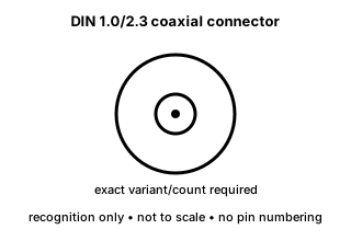
DIN 1.0/2.3 coaxial connector

DIN 1.0/2.3 is a compact coaxial connector family used in dense broadcast, telecom and instrumentation layouts.

Also called 1.0/2.3 DIN 1.0/2.3 1.0-2.3 coax

The compact 1.0/2.3 interface must be identified separately from BNC, HD-BNC and other dense coax families.

Look for

Look for the small cylindrical interface and documented 1.0/2.3 designation; coupling details vary by product.

Claim inspection dates: 2026-10-05, 2026-10-12, 2026-10-22 · Independent review pending

Image inspection / P232

See the view. Check its scope.

3 registered views for this reference. Different part examples are not automatically mates; all remain not to scale and independently unapproved.

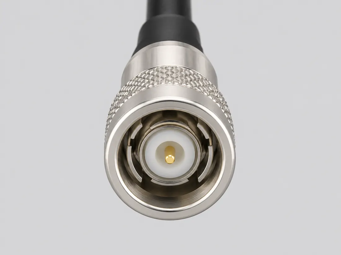
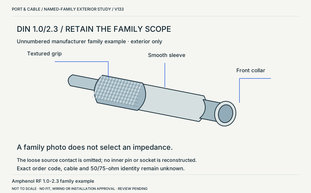
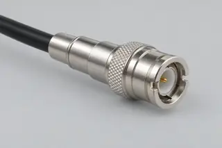
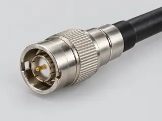
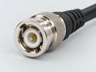
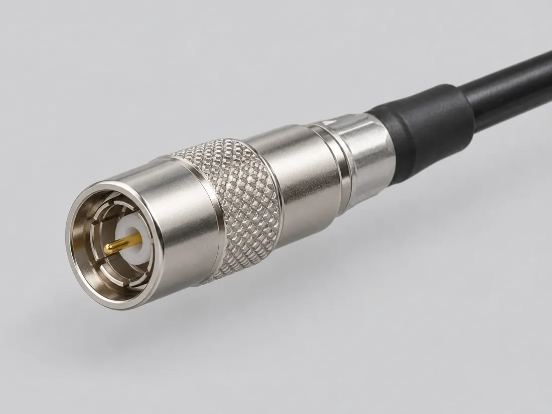
DIN 1.0/2.3 / named-family exterior. Named-family body study; no exact ordering code or selected impedance is established. (private workspace)

P232 / Source-observed physical study

DIN 1.0/2.3 / named-family exterior

Amphenol RF 1.0-2.3 family example

Oblique exterior: rear grip left, interface collar right · Cable plug / cable end

Not to scale. Technical and rights review pending.

Inspect view & provenance (private workspace)
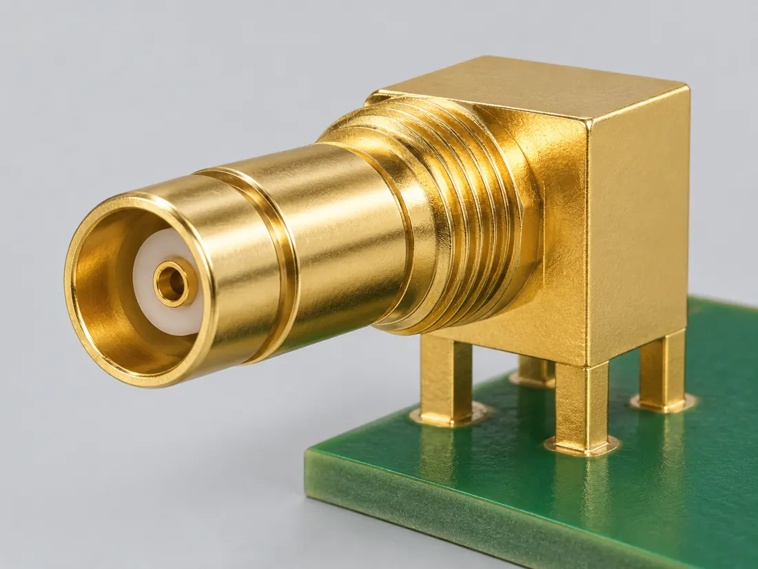
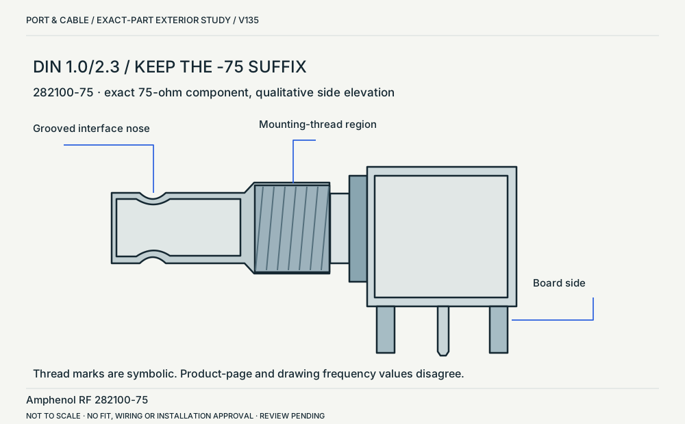
DIN 282100-75 / side elevation. Exact 75-ohm part, not 282100 without suffix. Thread detail is symbolic; frequency conflict remains unresolved. (private workspace)

P232 / Source-observed physical study

DIN 282100-75 / side elevation

Amphenol RF 282100-75

Side elevation: interface nose left, board-side below · Board header

Not to scale. Technical and rights review pending.

Inspect view & provenance (private workspace)
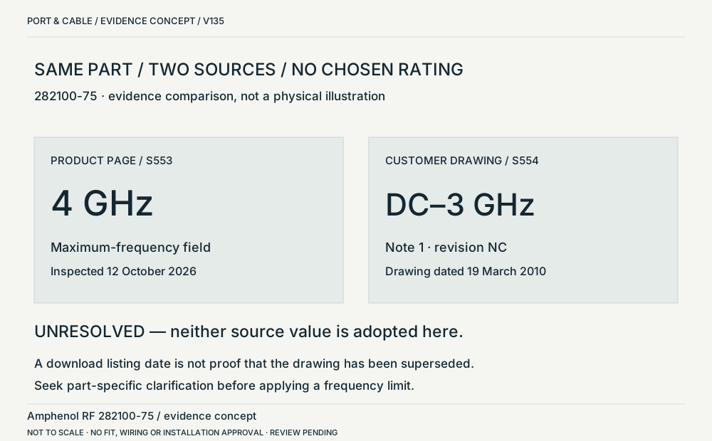
DIN 282100-75 / two source values. Concept only. Product page lists 4 GHz; drawing says DC–3 GHz. Neither value is adopted as a validated rating. (private workspace)

P232 / Concept — not physical geometry

DIN 282100-75 / two source values

Amphenol RF 282100-75 / evidence concept

Side-by-side text comparison; no physical geometry · Concept only

Not to scale. Technical and rights review pending.

Inspect view & provenance (private workspace)

The useful distinction

Recognize it. Then verify it.

DIN 1.0/2.3 is a compact coaxial connector family used in dense broadcast, telecom and instrumentation layouts. [C232A]

Amphenol RF describes the 1.0-2.3 family as push-pull locking connectors with separate 50-ohm and 75-ohm versions. [C232E]

The 1.0-2.3 page states that its typical specifications may not apply to every connector and that configuration can affect performance. [C232F]

The 1.0-2.3 page gives differing frequency descriptions for 75-ohm products in its narrative and table, so an unqualified family bandwidth remains unresolved. [C232G]

Amphenol RF identifies 282100-75 as a 75-ohm right-angle 1.0/2.3 jack with push-pull coupling, through-hole board termination and rear bulkhead mounting. [C232H]

The manufacturer lists 282100 as a separate 50-ohm part and 282100-75 as a 75-ohm part. [C232I]

For 282100-75, the product-page maximum-frequency field says 4 GHz, while note 1 of the linked drawing states DC–3 GHz. [C232J]

The 282100-75 drawing shows a grooved interface nose ahead of a threaded mounting neck and right-angle board body. [C232K]

The 282100-75 drawing labels its PCB mounting-hole diagram separately from the component exterior views. [C232L]

Exact example282100-75 only: Amphenol RF lists push-pull mating, a right-angle PCB through-hole jack with rear bulkhead mounting and solder contact termination. The body is brass, contacts are beryllium copper, and the insulator is PTFE. It is the75-ohm configuration. The page/drawing frequency conflict remains unresolved; no maximum frequency is adopted. [C232X]

Source-scoped identification facts

Each value retains its exact example, role and measurement axis. Facts from different parts must not be combined into an invented component.

Documented examples; not a mating drawing or compatibility approval
Mountingthrough-hole (Claim C232H)S553Recorded source-scoped values; named examples do not describe every family variant or establish compatibility. Only the complete 282100-75 identity; coupling, panel attachment and board termination remain separate.
Coupling / latchpush-pull (Claim C232A); push-pull (Claim C232B); push-pull (Claim C232E); push-pull (Claim C232H); Push-pull lockingS236 · S255 · S544 · S553 · S236Named source examples retain separate role, part, view and axis limits; values are not a universal family specification. V39 catalogue-expansion identification fact only; not independent technical approval, fabrication data, wiring instruction, protocol guarantee or end-to-end compatibility proof. V40 engineering-reference fact only; independent human review remains pending. This claim does not approve fabrication, rewiring, substitution, electrical safety, protocol support or end-to-end compatibility. Named manufacturer family; not an exact ordered component. Only the complete 282100-75 identity; coupling, panel attachment and board termination remain separate. Named series only, not every family part: Amphenol RF 1.0-2.3 product family. Family coupling is useful identification context but is not automatically counted as a polarization/keying fact.; No part suffix, row/contact pitch, dimensional axis, physical marking or universal performance limit inferred.
ManufacturerAmphenol RFS236Named source examples retain separate role, part, view and axis limits; values are not a universal family specification. Named series only, not every family part: Amphenol RF 1.0-2.3 product family. Family coupling is useful identification context but is not automatically counted as a polarization/keying fact.; No part suffix, row/contact pitch, dimensional axis, physical marking or universal performance limit inferred.
Series1.0-2.3S236Named source examples retain separate role, part, view and axis limits; values are not a universal family specification. Named series only, not every family part: Amphenol RF 1.0-2.3 product family. Family coupling is useful identification context but is not automatically counted as a polarization/keying fact.; No part suffix, row/contact pitch, dimensional axis, physical marking or universal performance limit inferred.

Not recorded: Nominal contacts, Positions / cavity span, Populated contacts, Contact rows, Contact pitch, Dimensions / axis, Connector role, Contact gender / arrangement, Keying / polarization, Shell / form, Exact part / implementation, Recorded markings, View convention. Unknown fields stay unknown; illustrations supply no measurements or pin assignments.

Recorded variant and source limits
  • Coupling style or polarity identity does not establish cable type, impedance, frequency range or system compatibility for a specific assembly.
  • No fabrication dimensions or mating-face contact locator is published.
Report a correction to these facts →

Bounded facts, visible unknowns

Specifications and limits

DIN 1.0/2.3 coaxial connector facts and limitations
Documented identificationDIN-style 1.0/2.3 compact coaxial connector family. [C232A]
Mechanical dimensionsNo independently reviewed mechanical drawing in V39; do not use this page for fabrication, fit testing or tolerance work.
Engineering pinoutSource-checked engineering profile available; independent review pending. Open engineering profile →
Verified device listNot included. Check exact device and accessory documentation.
A boundary, not an omission to guess around.

Use the source-backed form or position count only for identification. Resolve ratings, protocol, direction, wiring, cable construction and exact device support from the relevant equipment and component documentation.

Before you connect

What to check

  1. Identify the exact connector family and variant from the equipment or cable documentation.
  2. Keep shape, contact count, protocol, electrical rating and device support as separate facts.
  3. Do not force, rewire or adapt a connector from this recognition record; resolve the remaining requirements first.
Trace a supported connection class →

What is not established

This field note does not approve a connection, adapter, cable assembly, rewiring scheme or fabricated part. It intentionally omits unsupported pin assignments and mechanical tolerances.

Your next step

Move from the form to the requirement.

The source trail

Evidence for this page

AI-assisted inspection is not independent engineering review. Source scope and access limitations are disclosed below. Procedural checklists are editorial requirements, not hardware measurements.

Back to first citation ↑
C232ASource checked · pending review

Amphenol RF identifies 1.0/2.3 as a compact DIN-style coaxial connector family with push-pull interface options.

Amphenol RF · 1.0-2.3 connectors ↗

Locator: 1.0-2.3 overview
Access: public page. Identification/reference scope only. V39 does not convert this source into a universal pinout, fabrication drawing, electrical approval, protocol guarantee or end-to-end compatibility verdict.

S236: full source recordInspect review dependencies → (private workspace)

Claim scope: V39 catalogue-expansion identification fact only; not independent technical approval, fabrication data, wiring instruction, protocol guarantee or end-to-end compatibility proof.. Next review due 2027-01-03.

Back to first citation ↑
C232ESource checked · pending review

Amphenol RF describes the 1.0-2.3 family as push-pull locking connectors with separate 50-ohm and 75-ohm versions.

Amphenol RF · Amphenol RF 1.0-2.3 family — locking, impedance and limits ↗

Locator: Overview; Key Technical Details; separate 50 Ohm and 75 Ohm tables; typical-characteristics warning. Overview family photograph inspected separately.
Access: public page. Narrative 75-ohm frequency language differs from the 75-ohm table. Neither supplies a universal rating. Photograph contains a loose contact, omitted from the original study.

S544: full source recordInspect review dependencies → (private workspace)

Claim scope: Named manufacturer family; not an exact ordered component.. Next review due 2027-01-10.

Back to first citation ↑
C232FSource checked · pending review

The 1.0-2.3 page states that its typical specifications may not apply to every connector and that configuration can affect performance.

Amphenol RF · Amphenol RF 1.0-2.3 family — locking, impedance and limits ↗

Locator: Overview; Key Technical Details; separate 50 Ohm and 75 Ohm tables; typical-characteristics warning. Overview family photograph inspected separately.
Access: public page. Narrative 75-ohm frequency language differs from the 75-ohm table. Neither supplies a universal rating. Photograph contains a loose contact, omitted from the original study.

S544: full source recordInspect review dependencies → (private workspace)

Claim scope: Typical family data is not a measured assembly result.. Next review due 2027-01-10.

Back to first citation ↑
C232GSource checked · pending review

The 1.0-2.3 page gives differing frequency descriptions for 75-ohm products in its narrative and table, so an unqualified family bandwidth remains unresolved.

Amphenol RF · Amphenol RF 1.0-2.3 family — locking, impedance and limits ↗

Locator: Overview; Key Technical Details; separate 50 Ohm and 75 Ohm tables; typical-characteristics warning. Overview family photograph inspected separately.
Access: public page. Narrative 75-ohm frequency language differs from the 75-ohm table. Neither supplies a universal rating. Photograph contains a loose contact, omitted from the original study.

S544: full source recordInspect review dependencies → (private workspace)

Claim scope: No numeric frequency limit is selected or imported into engineering data.. Next review due 2027-01-10.

Back to first citation ↑
C232HSource checked · pending review

Amphenol RF identifies 282100-75 as a 75-ohm right-angle 1.0/2.3 jack with push-pull coupling, through-hole board termination and rear bulkhead mounting.

Amphenol RF · Amphenol RF 282100-75 — 75-ohm DIN board-jack fields ↗

Locator: Exact product heading and specification rows: 75 ohm, right angle, PCB through hole, rear bulkhead, push-pull and maximum-frequency field.
Access: public page. Exact named component only; no manufacturing dimensions, mating approval, PCB layout or equipment compatibility is established.

S553: full source recordInspect review dependencies → (private workspace)

Claim scope: Only the complete 282100-75 identity; coupling, panel attachment and board termination remain separate.. Next review due 2027-01-10.

Back to first citation ↑
C232ISource checked · pending review

The manufacturer lists 282100 as a separate 50-ohm part and 282100-75 as a 75-ohm part.

Amphenol RF · Amphenol RF 282100-75 — 75-ohm DIN board-jack fields ↗

Locator: Exact product heading and specification rows: 75 ohm, right angle, PCB through hole, rear bulkhead, push-pull and maximum-frequency field.
Access: public page. Exact named component only; no manufacturing dimensions, mating approval, PCB layout or equipment compatibility is established.

S553: full source recordAmphenol RF · Amphenol RF 282100 — separate 50-ohm DIN variant ↗

Locator: Exact part heading and impedance, coupling, orientation, termination and panel-mounting specification fields.
Access: public page. Exact named component only; no manufacturing dimensions, mating approval, PCB layout or equipment compatibility is established.

S555: full source recordInspect review dependencies → (private workspace)

Claim scope: These product identities are not interchangeable claims; the -75 suffix must not be dropped in the reference.. Next review due 2027-01-10.

Back to first citation ↑
C232JSource checked · pending review

For 282100-75, the product-page maximum-frequency field says 4 GHz, while note 1 of the linked drawing states DC–3 GHz.

Amphenol RF · Amphenol RF 282100-75 — 75-ohm DIN board-jack fields ↗

Locator: Exact product heading and specification rows: 75 ohm, right angle, PCB through hole, rear bulkhead, push-pull and maximum-frequency field.
Access: public page. Exact named component only; no manufacturing dimensions, mating approval, PCB layout or equipment compatibility is established.

S553: full source recordAmphenol RF · Amphenol RF 282100-75 — exact drawing and rating conflict ↗

Locator: Single-page drawing, revision NC dated 03/19/10; side elevation, board-side view, mounting-hole diagram and lower-right note 1 visually inspected.
Access: public pdf text. Exact named component only; no manufacturing dimensions, mating approval, PCB layout or equipment compatibility is established.

S554: full source recordInspect review dependencies → (private workspace)

Claim scope: Unresolved source conflict. Neither value is selected as a validated part rating or universal family maximum.. Next review due 2027-01-10.

Back to first citation ↑
C232KSource checked · pending review

The 282100-75 drawing shows a grooved interface nose ahead of a threaded mounting neck and right-angle board body.

Amphenol RF · Amphenol RF 282100-75 — exact drawing and rating conflict ↗

Locator: Single-page drawing, revision NC dated 03/19/10; side elevation, board-side view, mounting-hole diagram and lower-right note 1 visually inspected.
Access: public pdf text. Exact named component only; no manufacturing dimensions, mating approval, PCB layout or equipment compatibility is established.

S554: full source recordInspect review dependencies → (private workspace)

Claim scope: Qualitative recognition only. The mounting thread does not change the product page’s push-pull coupling designation; no thread dimensions are imported.. Next review due 2027-01-10.

Back to first citation ↑
C232LSource checked · pending review

The 282100-75 drawing labels its PCB mounting-hole diagram separately from the component exterior views.

Amphenol RF · Amphenol RF 282100-75 — exact drawing and rating conflict ↗

Locator: Single-page drawing, revision NC dated 03/19/10; side elevation, board-side view, mounting-hole diagram and lower-right note 1 visually inspected.
Access: public pdf text. Exact named component only; no manufacturing dimensions, mating approval, PCB layout or equipment compatibility is established.

S554: full source recordInspect review dependencies → (private workspace)

Claim scope: A mounting-hole drawing is not a face-view pinout or equipment wiring diagram. No contact numbering is supplied.. Next review due 2027-01-10.

Back to first citation ↑
C232XSource checked · pending review

Exact example282100-75 only: Amphenol RF lists push-pull mating, a right-angle PCB through-hole jack with rear bulkhead mounting and solder contact termination. The body is brass, contacts are beryllium copper, and the insulator is PTFE. It is the75-ohm configuration. The page/drawing frequency conflict remains unresolved; no maximum frequency is adopted.

Amphenol RF · Amphenol RF 282100-75 — 75-ohm DIN board-jack fields ↗

Locator: Exact product heading and specification rows: 75 ohm, right angle, PCB through hole, rear bulkhead, push-pull and maximum-frequency field.
Access: public page. Exact named component only; no manufacturing dimensions, mating approval, PCB layout or equipment compatibility is established.

S553: full source recordInspect review dependencies → (private workspace)

Claim scope: Only named Amphenol RF 282100-75 component example. For282100-75, the product page maximum-frequency field4GHz conflicts with linked drawingS554 DC-3GHz; both frequency claims remain withheld. Construction values are exact-part examples only.. Next review due 2027-01-20.

Suggest a correction to this field note →
Put this field note to work.

Add to discovery trayRecord an unsaved candidate (private workspace)

Candidate selection does not confirm the identity or capabilities of your physical item.

SOURCE-QUALIFIED COMPACT COAXIAL REFERENCE

Keep the component identity beside the specification.

Amphenol RF 1.0-2.3 family example

Component role
Push-pull locking family; exact pictured order code is unknown.
Source distinction
Separate 50-ohm and 75-ohm versions.
What this establishes
The exterior study retains the family scope, not an invented part number.
Not established
Loose source contact is omitted; exact impedance, cable and internal geometry unknown.
Next check
Identify the ordered part before checking the mating interface or electrical requirement.
Inspect the declared view → (private workspace)
Evidence, observation & limits

Inspected . C232E

Amphenol RF 1.0-2.3 family — locking, impedance and limits ↗
V133 observation: Overview; Key Technical Details; separate 50 Ohm and 75 Ohm tables; typical-characteristics warning. Overview family photograph inspected separately.
Canonical source record S544 dated 2026-10-12. The V133 visit is recorded separately; inherited source dates are unchanged.

No hardware test, independent technical approval or rights clearance is asserted.

Amphenol RF family narrative and tables

Component role
Separate 50-ohm and 75-ohm specification sections.
Source distinction
Typical characteristics may vary by connector configuration.
What this establishes
The 75-ohm narrative and table frequency descriptions remain unresolved.
Not established
No family-wide bandwidth or assembly performance approval.
Next check
Use consistent, exact-part manufacturer specifications and the complete connection path.

No source-observed physical view is selected for this row.

Evidence, observation & limits

Inspected . C232F · C232G

Amphenol RF 1.0-2.3 family — locking, impedance and limits ↗
V133 observation: Overview; Key Technical Details; separate 50 Ohm and 75 Ohm tables; typical-characteristics warning. Overview family photograph inspected separately.
Canonical source record S544 dated 2026-10-12. The V133 visit is recorded separately; inherited source dates are unchanged.

No hardware test, independent technical approval or rights clearance is asserted.

Read the compact coaxial reference and field guide →

SOURCE-QUALIFIED COAXIAL REFERENCE

Separate the interface, mounting and termination.

Amphenol RF 282100-75

Source / component role
75-ohm right-angle board jack with rear bulkhead mounting.
Documented distinction
Push-pull coupling; PCB through hole; grooved nose followed by mounting-thread region.
What this establishes
The exact -75 component now has its own source-observed exterior study.
Not established
No thread pitch, panel hole, internal contact profile, matching cable or qualified operating range is established.
Next check
Check interface, panel attachment and board termination as three separate requirements.
Inspect the declared view → (private workspace)
Evidence, observation & limits

Inspected . C232H · C232K · C232L

Amphenol RF 282100-75 — 75-ohm DIN board-jack fields ↗
V135 observation: Exact product heading and specification rows: 75 ohm, right angle, PCB through hole, rear bulkhead, push-pull and maximum-frequency field.
Canonical source record S553 dated 2026-10-12. Inherited source dates remain unchanged.

Amphenol RF 282100-75 — exact drawing and rating conflict ↗
V135 observation: Single-page drawing, revision NC dated 03/19/10; side elevation, board-side view, mounting-hole diagram and lower-right note 1 visually inspected.
Canonical source record S554 dated 2026-10-12. Inherited source dates remain unchanged.

No hardware test, independent technical approval or rights clearance is asserted.

Amphenol RF 282100 / without -75

Source / component role
50-ohm right-angle board jack; a different ordering identity.
Documented distinction
Both pages name push-pull coupling and rear bulkhead mounting, but their impedance fields differ.
What this establishes
Shared role words do not prove identical geometry or interchangeable equipment use.
Not established
The exact 282100 drawing was not inspected. The 282100-75 image is not used as its substitute.
Next check
Keep the full order code and required system impedance attached to each comparison.

No source-observed physical view is selected for this row.

Evidence, observation & limits

Inspected . C232I

Amphenol RF 282100-75 — 75-ohm DIN board-jack fields ↗
V135 observation: Exact product heading and specification rows: 75 ohm, right angle, PCB through hole, rear bulkhead, push-pull and maximum-frequency field.
Canonical source record S553 dated 2026-10-12. Inherited source dates remain unchanged.

Amphenol RF 282100 — separate 50-ohm DIN variant ↗
V135 observation: Exact part heading and impedance, coupling, orientation, termination and panel-mounting specification fields.
Canonical source record S555 dated 2026-10-12. Inherited source dates remain unchanged.

No hardware test, independent technical approval or rights clearance is asserted.

Amphenol RF 282100-75 / product page versus drawing

Source / component role
Two sources concerning the same exact part.
Documented distinction
Product page: maximum 4 GHz. Drawing note 1: DC–3 GHz.
What this establishes
Both source values remain visible as an unresolved conflict.
Not established
No final operating-frequency limit or evidence of a revision superseding another is established.
Next check
Obtain authoritative part-specific clarification before using a rating for design or replacement.

No source-observed physical view is selected for this row.

Evidence, observation & limits

Inspected . C232J

Amphenol RF 282100-75 — 75-ohm DIN board-jack fields ↗
V135 observation: Exact product heading and specification rows: 75 ohm, right angle, PCB through hole, rear bulkhead, push-pull and maximum-frequency field.
Canonical source record S553 dated 2026-10-12. Inherited source dates remain unchanged.

Amphenol RF 282100-75 — exact drawing and rating conflict ↗
V135 observation: Single-page drawing, revision NC dated 03/19/10; side elevation, board-side view, mounting-hole diagram and lower-right note 1 visually inspected.
Canonical source record S554 dated 2026-10-12. Inherited source dates remain unchanged.

No hardware test, independent technical approval or rights clearance is asserted.

Read the exact-component chart and field guide →

Evidence behind this page

Scope first. Source second. Approval separate.

5 linked sources · 10 scoped claims · 0 sources with inspection/access flags.

Page scope: catalogue_expansion_v39

Assessment 2026-10-22 · earliest scheduled source review 2027-01-03. This is a recorded-date assessment, not a live source check. Page-level independent review is not established by this panel.

Inspect 5 source scopes, access limits and dates

S236 · 1.0-2.3 connectors

Amphenol RF · Manufacturer / product-owner domain · inspected 2026-10-05 · due 2027-01-03

Within inspection window

Scoped support: Identifies the DIN-style 1.0/2.3 coaxial connector family and its compact push-pull interface.

Not established / limitations: Identification/reference scope only. V39 does not convert this source into a universal pinout, fabrication drawing, electrical approval, protocol guarantee or end-to-end compatibility verdict.

Locator: 1.0-2.3 overview

S544 · Amphenol RF 1.0-2.3 family — locking, impedance and limits

Amphenol RF · Manufacturer / product-owner domain · inspected 2026-10-12 · due 2027-01-10

Within inspection window

Scoped support: Named family only. Family photograph has no exact ordering code, impedance or cable identity.

Not established / limitations: Narrative 75-ohm frequency language differs from the 75-ohm table. Neither supplies a universal rating. Photograph contains a loose contact, omitted from the original study.

Locator: Overview; Key Technical Details; separate 50 Ohm and 75 Ohm tables; typical-characteristics warning. Overview family photograph inspected separately.

S553 · Amphenol RF 282100-75 — 75-ohm DIN board-jack fields

Amphenol RF · Manufacturer / product-owner domain · inspected 2026-10-12 · due 2027-01-10

Within inspection window

Scoped support: Only exact part 282100-75. Page lists maximum frequency 4 GHz; linked drawing states DC–3 GHz. The conflict is unresolved.

Not established / limitations: Exact named component only; no manufacturing dimensions, mating approval, PCB layout or equipment compatibility is established.

Locator: Exact product heading and specification rows: 75 ohm, right angle, PCB through hole, rear bulkhead, push-pull and maximum-frequency field.

S554 · Amphenol RF 282100-75 — exact drawing and rating conflict

Amphenol RF · Manufacturer / product-owner domain · inspected 2026-10-12 · due 2027-01-10

Within inspection window

Scoped support: Exact part 282100-75 drawing states DC–3 GHz, unlike the product page. Side study is qualitative; PCB contact geometry, pitch and tolerances are omitted.

Not established / limitations: Exact named component only; no manufacturing dimensions, mating approval, PCB layout or equipment compatibility is established.

Locator: Single-page drawing, revision NC dated 03/19/10; side elevation, board-side view, mounting-hole diagram and lower-right note 1 visually inspected.

S555 · Amphenol RF 282100 — separate 50-ohm DIN variant

Amphenol RF · Manufacturer / product-owner domain · inspected 2026-10-12 · due 2027-01-10

Within inspection window

Scoped support: This is the separately identified 50-ohm 282100, not 282100-75. Its drawing returned unsupported content type and was not visually inspected; no substitute image is assigned.

Not established / limitations: Exact named component only; no manufacturing dimensions, mating approval, PCB layout or equipment compatibility is established.

Locator: Exact part heading and impedance, coupling, orientation, termination and panel-mounting specification fields.

Trace 10 claims to their source records

C232A · P232

Amphenol RF identifies 1.0/2.3 as a compact DIN-style coaxial connector family with push-pull interface options.

Claim scope: V39 catalogue-expansion identification fact only; not independent technical approval, fabrication data, wiring instruction, protocol guarantee or end-to-end compatibility proof.

Source links: S236 · Evidence trail → (private workspace)

C232E · P232

Amphenol RF describes the 1.0-2.3 family as push-pull locking connectors with separate 50-ohm and 75-ohm versions.

Claim scope: Named manufacturer family; not an exact ordered component.

Source links: S544 · Evidence trail → (private workspace)

C232F · P232

The 1.0-2.3 page states that its typical specifications may not apply to every connector and that configuration can affect performance.

Claim scope: Typical family data is not a measured assembly result.

Source links: S544 · Evidence trail → (private workspace)

C232G · P232

The 1.0-2.3 page gives differing frequency descriptions for 75-ohm products in its narrative and table, so an unqualified family bandwidth remains unresolved.

Claim scope: No numeric frequency limit is selected or imported into engineering data.

Source links: S544 · Evidence trail → (private workspace)

C232H · P232

Amphenol RF identifies 282100-75 as a 75-ohm right-angle 1.0/2.3 jack with push-pull coupling, through-hole board termination and rear bulkhead mounting.

Claim scope: Only the complete 282100-75 identity; coupling, panel attachment and board termination remain separate.

Source links: S553 · Evidence trail → (private workspace)

C232I · P232

The manufacturer lists 282100 as a separate 50-ohm part and 282100-75 as a 75-ohm part.

Claim scope: These product identities are not interchangeable claims; the -75 suffix must not be dropped in the reference.

Source links: S553 · S555 · Evidence trail → (private workspace)

C232J · P232

For 282100-75, the product-page maximum-frequency field says 4 GHz, while note 1 of the linked drawing states DC–3 GHz.

Claim scope: Unresolved source conflict. Neither value is selected as a validated part rating or universal family maximum.

Source links: S553 · S554 · Evidence trail → (private workspace)

C232K · P232

The 282100-75 drawing shows a grooved interface nose ahead of a threaded mounting neck and right-angle board body.

Claim scope: Qualitative recognition only. The mounting thread does not change the product page’s push-pull coupling designation; no thread dimensions are imported.

Source links: S554 · Evidence trail → (private workspace)

C232L · P232

The 282100-75 drawing labels its PCB mounting-hole diagram separately from the component exterior views.

Claim scope: A mounting-hole drawing is not a face-view pinout or equipment wiring diagram. No contact numbering is supplied.

Source links: S554 · Evidence trail → (private workspace)

C232X · P232

Exact example282100-75 only: Amphenol RF lists push-pull mating, a right-angle PCB through-hole jack with rear bulkhead mounting and solder contact termination. The body is brass, contacts are beryllium copper, and the insulator is PTFE. It is the75-ohm configuration. The page/drawing frequency conflict remains unresolved; no maximum frequency is adopted.

Claim scope: Only named Amphenol RF 282100-75 component example. For282100-75, the product page maximum-frequency field4GHz conflicts with linked drawingS554 DC-3GHz; both frequency claims remain withheld. Construction values are exact-part examples only.

Source links: S553 · Evidence trail → (private workspace)

Prepare this page for review → (private workspace)Read the evidence method →

Recorded evidence only. An inspection date, publisher label, source link or generated packet is not independent technical review, hardware testing, fabrication approval or a compatibility verdict.