FIELD GUIDESource-led reference

E232 · No electrical assignment published

DIN 1.0/2.3 coaxial connector engineering reference

Family-level coupling boundary only; exact electrical performance and cable suitability remain configuration-dependent. Exact example282100-75 only: Amphenol RF lists push-pull mating, a right-angle PCB through-hole jack with rear bulkhead mounting and solder contact termination. The body is brass, contacts are beryllium copper, and the insulator is PTFE. It is the75-ohm configuration. The page/drawing frequency conflict remains unresolved; no maximum frequency is adopted.

Source checked · no independent review claimed · Fabrication approved: no
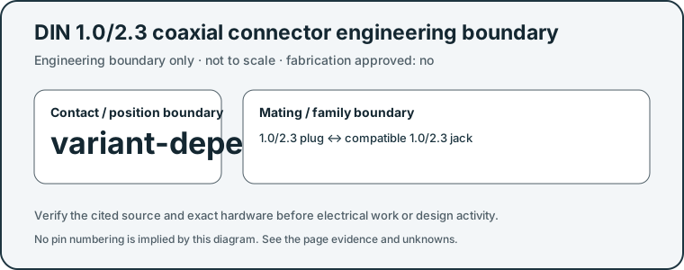
DIN 1.0/2.3 coaxial connector engineering boundary original orientation schematic
Original V40 engineering boundary schematic; not to scale and not a fabrication, gauging, wiring or mating-face locator drawing.

Orientation

How to read this profile

V40 publishes no face-view pin locator from this family-level source.

Source-scoped identification facts

Each value retains its exact example, role and measurement axis. Facts from different parts must not be combined into an invented component.

Documented examples; not a mating drawing or compatibility approval
Mountingthrough-hole (Claim C232H)S553Recorded source-scoped values; named examples do not describe every family variant or establish compatibility. Only the complete 282100-75 identity; coupling, panel attachment and board termination remain separate.
Coupling / latchpush-pull (Claim C232A); push-pull (Claim C232B); push-pull (Claim C232E); push-pull (Claim C232H); Push-pull lockingS236 · S255 · S544 · S553 · S236Named source examples retain separate role, part, view and axis limits; values are not a universal family specification. V39 catalogue-expansion identification fact only; not independent technical approval, fabrication data, wiring instruction, protocol guarantee or end-to-end compatibility proof. V40 engineering-reference fact only; independent human review remains pending. This claim does not approve fabrication, rewiring, substitution, electrical safety, protocol support or end-to-end compatibility. Named manufacturer family; not an exact ordered component. Only the complete 282100-75 identity; coupling, panel attachment and board termination remain separate. Named series only, not every family part: Amphenol RF 1.0-2.3 product family. Family coupling is useful identification context but is not automatically counted as a polarization/keying fact.; No part suffix, row/contact pitch, dimensional axis, physical marking or universal performance limit inferred.
ManufacturerAmphenol RFS236Named source examples retain separate role, part, view and axis limits; values are not a universal family specification. Named series only, not every family part: Amphenol RF 1.0-2.3 product family. Family coupling is useful identification context but is not automatically counted as a polarization/keying fact.; No part suffix, row/contact pitch, dimensional axis, physical marking or universal performance limit inferred.
Series1.0-2.3S236Named source examples retain separate role, part, view and axis limits; values are not a universal family specification. Named series only, not every family part: Amphenol RF 1.0-2.3 product family. Family coupling is useful identification context but is not automatically counted as a polarization/keying fact.; No part suffix, row/contact pitch, dimensional axis, physical marking or universal performance limit inferred.

Not recorded: Nominal contacts, Positions / cavity span, Populated contacts, Contact rows, Contact pitch, Dimensions / axis, Connector role, Contact gender / arrangement, Keying / polarization, Shell / form, Exact part / implementation, Recorded markings, View convention. Unknown fields stay unknown; illustrations supply no measurements or pin assignments.

Recorded variant and source limits
  • Coupling style or polarity identity does not establish cable type, impedance, frequency range or system compatibility for a specific assembly.
  • No fabrication dimensions or mating-face contact locator is published.
Report a correction to these facts →

Unknowns stay unknown.

  • Coupling style or polarity identity does not establish cable type, impedance, frequency range or system compatibility for a specific assembly.
  • No fabrication dimensions or mating-face contact locator is published.
  • For282100-75, the product page maximum-frequency field4GHz conflicts with linked drawingS554 DC-3GHz; both frequency claims remain withheld. Construction values are exact-part examples only.

Your next step

Use the detail without guessing past its limits.

Source trail

Claims and sources

C232Bsource checked

Amphenol RF identifies the 1.0/2.3 family as using push-pull coupling.

Amphenol RF · 1.0/2.3 RF connector family ↗
1.0/2.3 connector family · Engineering-reference scope only. V40 does not turn this source into fabrication approval, electrical safety approval, protocol guarantee, safe substitution or end-to-end compatibility proof.

C232Xsource checked

Exact example282100-75 only: Amphenol RF lists push-pull mating, a right-angle PCB through-hole jack with rear bulkhead mounting and solder contact termination. The body is brass, contacts are beryllium copper, and the insulator is PTFE. It is the75-ohm configuration. The page/drawing frequency conflict remains unresolved; no maximum frequency is adopted.

Amphenol RF · Amphenol RF 282100-75 — 75-ohm DIN board-jack fields ↗
Exact product heading and specification rows: 75 ohm, right angle, PCB through hole, rear bulkhead, push-pull and maximum-frequency field. · Exact named component only; no manufacturing dimensions, mating approval, PCB layout or equipment compatibility is established.

2 source records support this profile. No independent engineering review or hardware validation is claimed.

Evidence behind this page

Scope first. Source second. Approval separate.

2 linked sources · 2 scoped claims · 0 sources with inspection/access flags.

Page scope: Original V40 engineering boundary schematic; not to scale and not a fabrication, gauging, wiring or mating-face locator drawing.

Assessment 2026-10-22 · earliest scheduled source review 2027-01-03. This is a recorded-date assessment, not a live source check. Page-level independent review is not established by this panel.

Inspect 2 source scopes, access limits and dates

S255 · 1.0/2.3 RF connector family

Amphenol RF · Manufacturer / product-owner domain · inspected 2026-10-05 · due 2027-01-03

Within inspection window

Scoped support: Engineering boundary: the 1.0/2.3 RF family uses push-pull coupling in the inspected manufacturer reference; V40 does not infer cable or broadcast-system compatibility.

Not established / limitations: Engineering-reference scope only. V40 does not turn this source into fabrication approval, electrical safety approval, protocol guarantee, safe substitution or end-to-end compatibility proof.

Locator: 1.0/2.3 connector family

S553 · Amphenol RF 282100-75 — 75-ohm DIN board-jack fields

Amphenol RF · Manufacturer / product-owner domain · inspected 2026-10-12 · due 2027-01-10

Within inspection window

Scoped support: Only exact part 282100-75. Page lists maximum frequency 4 GHz; linked drawing states DC–3 GHz. The conflict is unresolved.

Not established / limitations: Exact named component only; no manufacturing dimensions, mating approval, PCB layout or equipment compatibility is established.

Locator: Exact product heading and specification rows: 75 ohm, right angle, PCB through hole, rear bulkhead, push-pull and maximum-frequency field.

Trace 2 claims to their source records

C232B · P232

Amphenol RF identifies the 1.0/2.3 family as using push-pull coupling.

Claim scope: V40 engineering-reference fact only; independent human review remains pending. This claim does not approve fabrication, rewiring, substitution, electrical safety, protocol support or end-to-end compatibility.

Source links: S255 · Evidence trail → (private workspace)

C232X · P232

Exact example282100-75 only: Amphenol RF lists push-pull mating, a right-angle PCB through-hole jack with rear bulkhead mounting and solder contact termination. The body is brass, contacts are beryllium copper, and the insulator is PTFE. It is the75-ohm configuration. The page/drawing frequency conflict remains unresolved; no maximum frequency is adopted.

Claim scope: Only named Amphenol RF 282100-75 component example. For282100-75, the product page maximum-frequency field4GHz conflicts with linked drawingS554 DC-3GHz; both frequency claims remain withheld. Construction values are exact-part examples only.

Source links: S553 · Evidence trail → (private workspace)

Prepare this page for review → (private workspace)Read the evidence method →

Recorded evidence only. An inspection date, publisher label, source link or generated packet is not independent technical review, hardware testing, fabrication approval or a compatibility verdict.