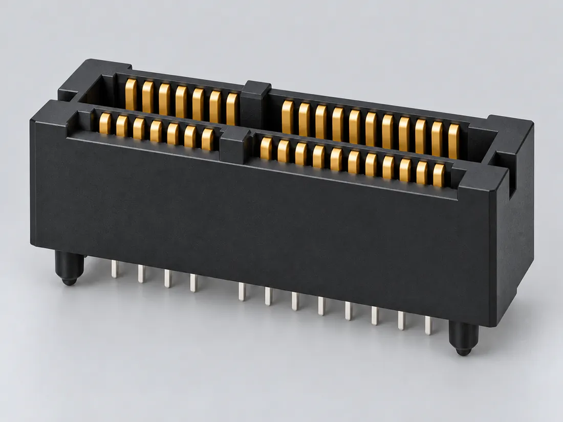
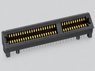
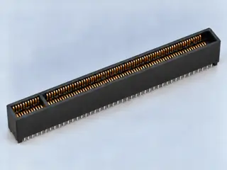
Three-quarter view Computer-generated illustration with prior AI visual review. Not a photograph, measurement or compatibility check. Independent technical and rights review pending.
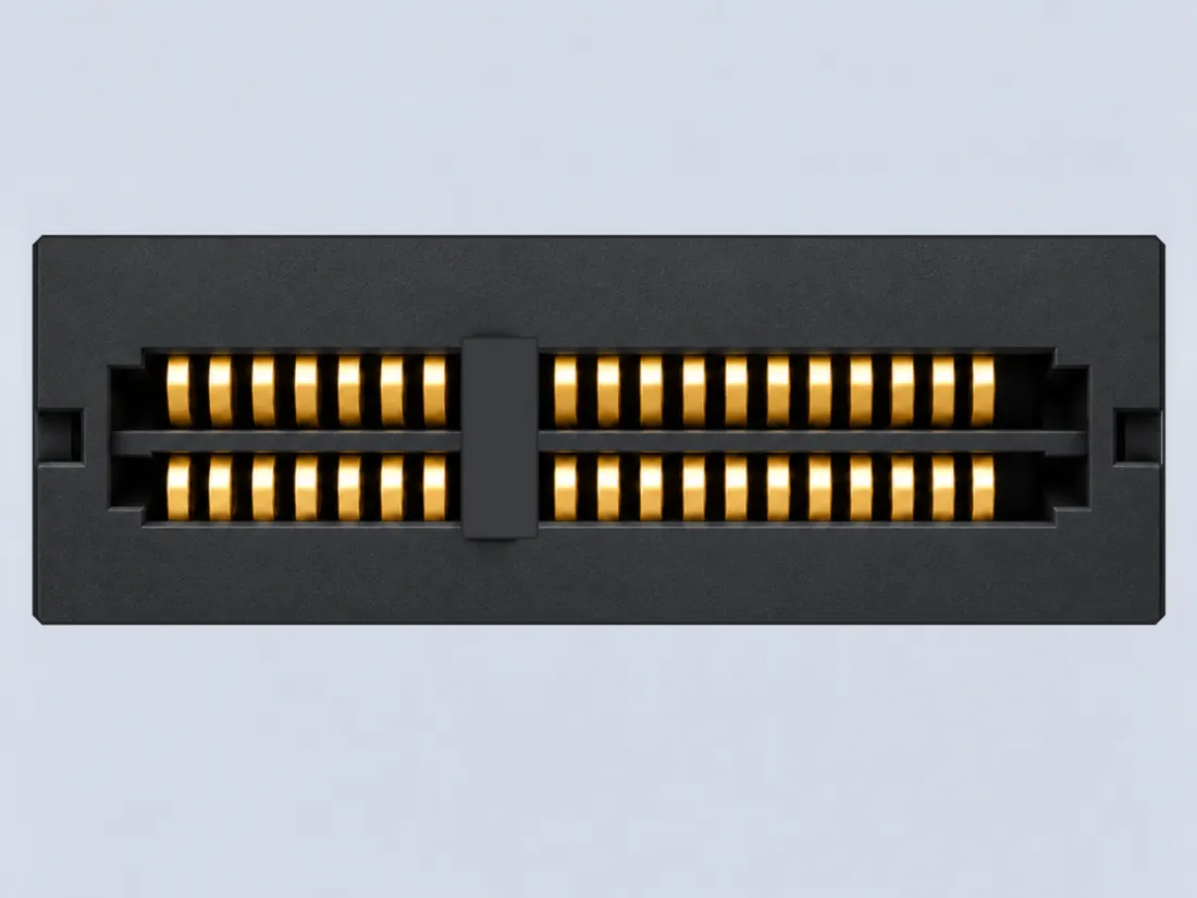
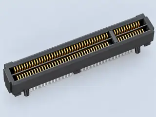
Mating face Computer-generated illustration with prior AI visual review. Not a photograph, measurement or compatibility check. Independent technical and rights review pending.
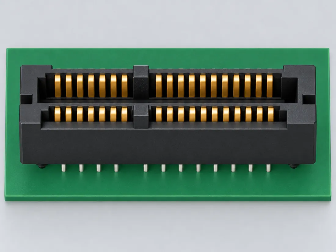
Fitted in place Computer-generated illustration with prior AI visual review. Not a photograph, measurement or compatibility check. Independent technical and rights review pending.
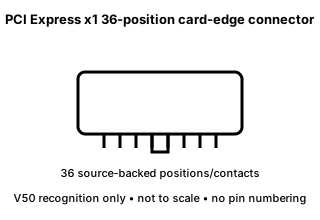
Recognition drawing Original schematic, not to scale. Drawing review pending.
INTERNAL SYSTEMS / EXPANSION
PCIe x1 refers to a keyed physical card edge and lane class
No. The existing canonical record identifies a 36-position PCI Express x1 card-edge component. Fit may be a first screening step, but generation, lane availability, slot power, firmware options, chassis clearance and expansion-card support must be checked independently on the target motherboard.
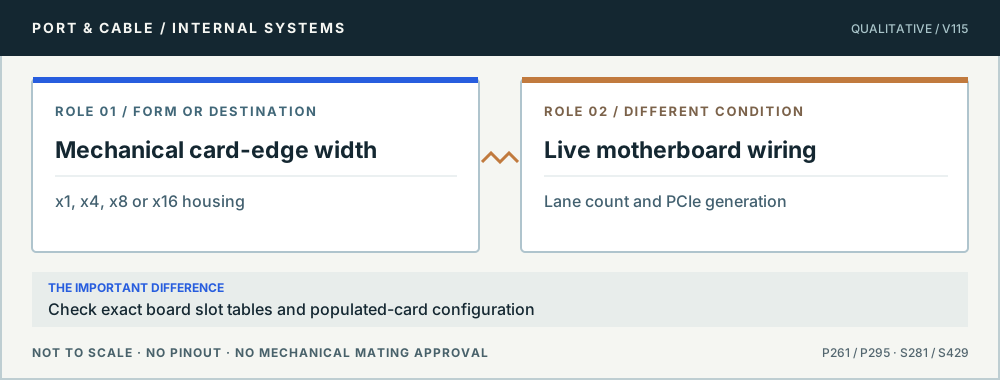
Slot length vs enabled link. Original qualitative role diagram; not mechanical artwork, not to scale or a wiring map. Source context S281 · S429.
Three checks before proceeding
Check the board’s expansion-slot matrix and BIOS restrictions.
Confirm the exact card’s lane, power and cooling needs.
Verify physical obstruction and available chassis slots before purchasing.
One mistake to avoid
Interpreting identical-looking x1 socket plastic as evidence of support for a special-purpose adapter or riser.
Claim-specific evidence remains in the canonical record. Concept diagrams do not show any safe wiring or mechanical mating geometry.
Visual correction / P295 / Source-scoped
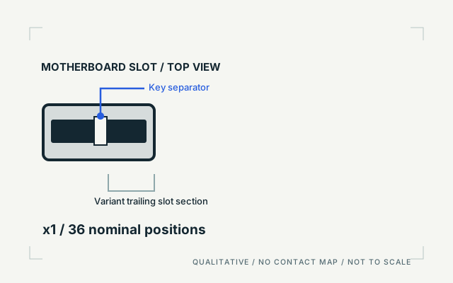
The key stays; the slot length changes.
SLOT / TOP VIEW
Unlike the inherited symbol, this diagram shows a receptacle channel, shared key separator and trailing-length distinction. It is not to scale and does not show contact mapping.
Top-facing conceptual slot opening; not the add-in card edge, a rear solder view, or an insertion instruction.
Look for
Short expansion slot with a short leading segment, a key gap, and a short trailing section.
Nominal position class: 36 positions. The marks and proportions in this drawing are not pins or mechanical dimensions.
Keep the host-specific question open
Source-supported family key and position-class recognition. Stylized channel; hatching is not the contact arrangement, and there are no real tolerances, pins or measured dimensions.
A physical slot class does not prove its electrical lane wiring, generation or available power.
Checked 2026-10-09. New, original schematic; no source CAD, third-party photo or logo bundled. No independent engineering certification is claimed; underlying source review dates are unchanged.
The useful distinction
Recognize it. Then verify it.
Amphenol documents the PCI Express x1 card-edge form with 36 positions in its standard connector range. [C295A]
Source-scoped identification facts
Each value retains its exact example, role and measurement axis. Facts from different parts must not be combined into an invented component.
Documented examples; not a mating drawing or compatibility approval
Nominal contacts
36S336Source-backed nominal position/contact count for identification: 36. Not a pinout or manufacturing drawing.
Positions / cavity span
36 (Claim C295A); 36 (Claim C295B)S336 · S357Recorded source-scoped values; named examples do not describe every family variant or establish compatibility. V50 identification fact only; no wiring, protocol compatibility, installation or fabrication approval is inferred. Mechanical/contact-count context only; no PCIe generation, lane enablement, logical pin assignment or board-layout approval is inferred.
Contact pitch
1 mm Contact pitch (Recorded example component); 1 mm Source-described pitch / centerline (Claim C295B); 1 mm centerlineS357 · S336Named source examples retain separate role, part, view and axis limits; values are not a universal family specification. example_component; PCI Express x1 card-edge connector example Mechanical/contact-count context only; no PCIe generation, lane enablement, logical pin assignment or board-layout approval is inferred. Named series only, not every family part: Amphenol PCI Express Gen3 36-position family. Documented role: socket. Family source explicitly mapsx1=36,x4=64,x8=98; no exactpart or connector size derived. Standalone retention mechanism varies by product.
Connector role
card-edge; socketS336 · S357 · S336Named source examples retain separate role, part, view and axis limits; values are not a universal family specification. PCI Express x1 card-edge connector example Named series only, not every family part: Amphenol PCI Express Gen3 36-position family. Documented role: socket. Family source explicitly mapsx1=36,x4=64,x8=98; no exactpart or connector size derived. Standalone retention mechanism varies by product.
Manufacturer
Amphenol Communications SolutionsS336Named source examples retain separate role, part, view and axis limits; values are not a universal family specification. Named series only, not every family part: Amphenol PCI Express Gen3 36-position family. Documented role: socket. Family source explicitly mapsx1=36,x4=64,x8=98; no exactpart or connector size derived. Standalone retention mechanism varies by product.
Series
PCI Express Gen3 36-position card-edgeS336Named source examples retain separate role, part, view and axis limits; values are not a universal family specification. Named series only, not every family part: Amphenol PCI Express Gen3 36-position family. Documented role: socket. Family source explicitly mapsx1=36,x4=64,x8=98; no exactpart or connector size derived. Standalone retention mechanism varies by product.
Not recorded: Populated contacts, Contact rows, Dimensions / axis, Contact gender / arrangement, Mounting, Coupling / latch, Keying / polarization, Shell / form, Exact part / implementation, Recorded markings, View convention. Unknown fields stay unknown; illustrations supply no measurements or pin assignments.
Recorded variant and source limits
The card-edge form does not by itself establish PCIe generation, active lanes, bifurcation, electrical compliance, power budget or motherboard behavior.
Pitch and position count do not constitute a fabrication drawing, slot-compliance gauge or board-layout approval.
PICMG design-guide x1 reference slot: Source schematic contact identities A1-A18 / B1-B18. The two columns are schematic symbol sides, not a verified mating-face or solder-side view.
Not included. Check exact device and accessory documentation.
A boundary, not an omission to guess around.
Use only the source-backed family, role or position count for identification. Resolve electrical ratings, protocol generation, lane wiring, signal assignment, cable construction and exact device support from the relevant equipment and component documentation.
Before you connect
What to check
Identify the exact connector family and variant from the equipment or component documentation.
Keep physical form, contact count, protocol, electrical rating and device support as separate facts.
Do not force, rewire, adapt or install from this recognition record; resolve the remaining requirements first.
Choose the exact wiring. Pin numbers follow its stated view; a schematic does not establish physical positions. Check your exact device before wiring.
What the status labels mean
Confirmed
Recorded research passes agree within this variant; this is not independent human review or hardware validation.
Single source
Only one underlying document, or one pass, supports this assignment.
Device-specific
Supported for the named equipment or wiring only. Check your device’s manual.
Unverified
Missing or conflicting evidence. Do not wire from this row.
Not connected
The source explicitly says NC, no contact or no pin for this wiring.
What is not established
This field note does not approve a connection, adapter, cable assembly, rewiring scheme, energized-work procedure or fabricated part. It intentionally omits unsupported pin assignments and mechanical tolerances.
AI-assisted inspection is not independent engineering review. Source scope and access limitations are disclosed below. Procedural checklists are editorial requirements, not hardware measurements.
Locator: Product-series description and standard pin-count/lane-width summary Access: public page. Source-backed identification does not establish universal wiring, protocol generation, device compatibility, safe installation or fabrication approval.
Claim scope: V50 identification fact only; no wiring, protocol compatibility, installation or fabrication approval is inferred.. Next review due 2027-01-04.
Assessment 2026-10-22 · earliest scheduled source review 2027-01-04. This is a recorded-date assessment, not a live source check. Page-level independent review is not established by this panel.
Scoped support: Manufacturer series reference for the PCI Express x1 mechanical/contact-count form only.
Not established / limitations: Source-backed identification does not establish universal wiring, protocol generation, device compatibility, safe installation or fabrication approval.
Locator: Product-series description and standard pin-count/lane-width summary
Trace 1 claims to their source records
C295A · P295
Amphenol identifies the standard PCI Express x1 card-edge connector form with 36 positions/contacts in its PCIe connector range.
Claim scope: V50 identification fact only; no wiring, protocol compatibility, installation or fabrication approval is inferred.
Recorded evidence only. An inspection date, publisher label, source link or generated packet is not independent technical review, hardware testing, fabrication approval or a compatibility verdict.