FIELD GUIDESource-led reference

P209 / Legacy computer / Connector

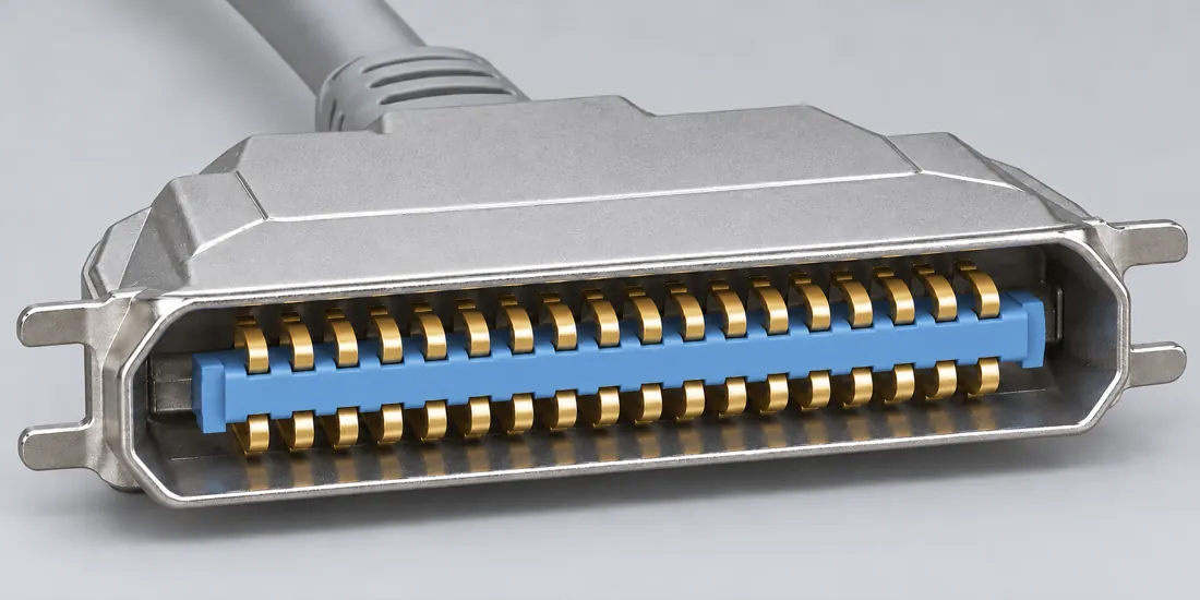
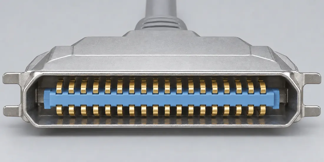
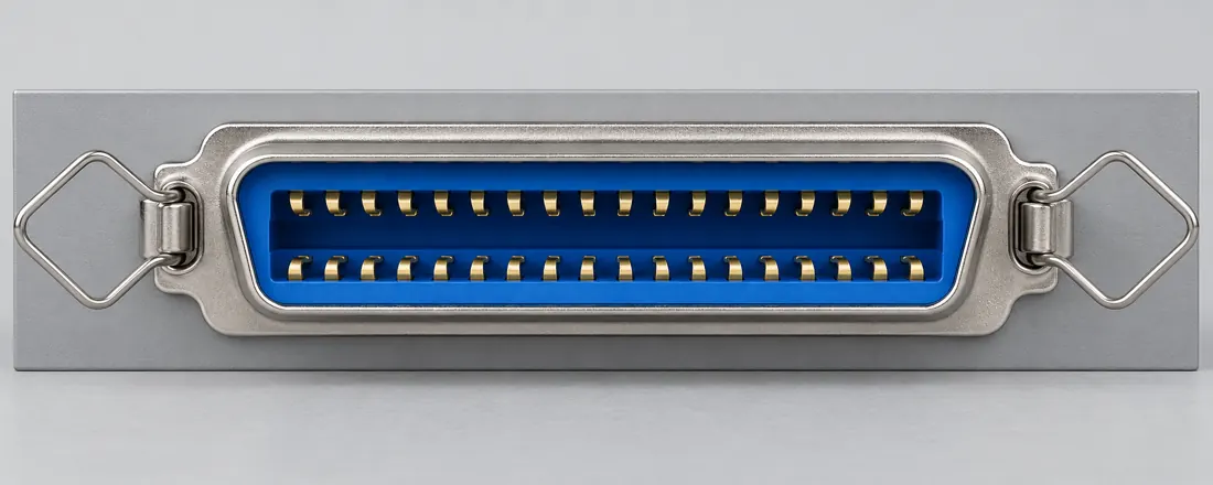
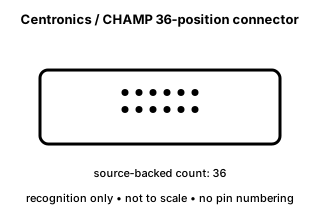
Centronics / CHAMP 36-position connector

The 36-position CHAMP/Centronics-style connector is a legacy ribbon-style connector form associated with parallel-peripheral applications.

Also called Centronics 36 CHAMP 36 IEEE 1284 printer connector 36 pin parallel

A 36-position ribbon connector outline is not proof of IEEE 1284 mode, wiring or device compatibility.

Look for

Count positions and confirm the equipment/cable specification; avoid choosing by the colloquial “printer connector” name alone.

Claim inspection dates: 2026-10-05 · Independent review pending

The useful distinction

Recognize it. Then verify it.

The 36-position CHAMP/Centronics-style connector is a legacy ribbon-style connector form associated with parallel-peripheral applications. [C209A]

Source-scoped identification facts

Each value retains its exact example, role and measurement axis. Facts from different parts must not be combined into an invented component.

Documented examples; not a mating drawing or compatibility approval
Nominal contacts36S212Source-backed position count only; no parallel-port pin assignment is published.
Positions / cavity span36 (Claim C209A)S212Recorded source-scoped values; named examples do not describe every family variant or establish compatibility. V36 catalogue-expansion identification fact only; not independent technical approval, fabrication data, wiring instruction or end-to-end compatibility proof.
Contact rows2 (1734044-1)S212Named source examples retain separate role, part, view and axis limits; values are not a universal family specification. 1734044-1. Documented role: socket. 1.57mm recommendedPCB thickness is excluded from connector dimensions. No numbered mating face or universalCentronics wiring inferred.
Contact pitch2.16 mm published contact centerline (1734044-1)S212Named source examples retain separate role, part, view and axis limits; values are not a universal family specification. 1734044-1. Documented role: socket. 1.57mm recommendedPCB thickness is excluded from connector dimensions. No numbered mating face or universalCentronics wiring inferred.
Dimensions / axis4.3 mm row-to-row spacing (1734044-1)S212Named source examples retain separate role, part, view and axis limits; values are not a universal family specification. 1734044-1. Documented role: socket. 1.57mm recommendedPCB thickness is excluded from connector dimensions. No numbered mating face or universalCentronics wiring inferred.
Connector rolesocket (1734044-1)S212Named source examples retain separate role, part, view and axis limits; values are not a universal family specification. 1734044-1. Documented role: socket. 1.57mm recommendedPCB thickness is excluded from connector dimensions. No numbered mating face or universalCentronics wiring inferred.
Coupling / latchBail lock or round-head UNC4/40 screw mating retention (1734044-1)S212Named source examples retain separate role, part, view and axis limits; values are not a universal family specification. 1734044-1. Documented role: socket. 1.57mm recommendedPCB thickness is excluded from connector dimensions. No numbered mating face or universalCentronics wiring inferred.
ManufacturerTE Connectivity (1734044-1)S212Named source examples retain separate role, part, view and axis limits; values are not a universal family specification. 1734044-1. Documented role: socket. 1.57mm recommendedPCB thickness is excluded from connector dimensions. No numbered mating face or universalCentronics wiring inferred.
SeriesCHAMP .085 (1734044-1)S212Named source examples retain separate role, part, view and axis limits; values are not a universal family specification. 1734044-1. Documented role: socket. 1.57mm recommendedPCB thickness is excluded from connector dimensions. No numbered mating face or universalCentronics wiring inferred.
Exact part / implementation1734044-1 (1734044-1)S212Named source examples retain separate role, part, view and axis limits; values are not a universal family specification. 1734044-1. Documented role: socket. 1.57mm recommendedPCB thickness is excluded from connector dimensions. No numbered mating face or universalCentronics wiring inferred.

Not recorded: Populated contacts, Contact gender / arrangement, Mounting, Keying / polarization, Shell / form, Recorded markings, View convention. Unknown fields stay unknown; illustrations supply no measurements or pin assignments.

Recorded variant and source limits
  • Check the exact device manual before wiring or applying power.
  • IBM Graphics Printer parallel interface (printer side, 36-pin Amphenol 57-30360): Contact numbers from IBM table; 'Direction' is as viewed from the printer.
  • Epson AcuLaser C2000 parallel interface (IEEE 1284-B receptacle, printer side): Contact numbers from Epson table; direction as viewed from the printer.
  • Epson EPL-5800 laser printer parallel interface (IEEE 1284-B connector): Contact numbers 1-36 of the printer's 36-position ribbon (IEEE 1284-B) receptacle; directions are into/out of the printer. No face view transferred.
  • Epson AcuLaser C2000 parallel interface (IEEE 1284-B connector; 'IEEE 1284-I compliant'): Contact numbers 1-36 of the printer's 36-position ribbon (IEEE 1284-B) receptacle; directions are into/out of the printer. No face view transferred.
Report a correction to these facts →

Bounded facts, visible unknowns

Specifications and limits

Centronics / CHAMP 36-position connector facts and limitations
Documented identification36-position CHAMP / Centronics-style connector form. [C209A]
Mechanical dimensionsNo independently reviewed mechanical drawing in V36; do not use this page for fabrication, fit testing or tolerance work.
Engineering pinoutSource-checked engineering profile available; independent review pending. Open engineering profile →
Verified device listNot included. Check exact device and accessory documentation.
A boundary, not an omission to guess around.

Use the source-backed form or position count only for identification. Resolve ratings, protocol, direction, wiring, cable construction and exact device support from the relevant equipment and component documentation.

Before you connect

What to check

  1. Identify the exact connector family and variant from the equipment or cable documentation.
  2. Keep shape, contact count, protocol, electrical rating and device support as separate facts.
  3. Do not force, rewire or adapt a connector from this recognition record; resolve the remaining requirements first.
Trace a supported connection class →

Pins & wiring

Pinout

Choose the exact wiring. Pin numbers follow its stated view; a schematic does not establish physical positions. Check your exact device before wiring.

What the status labels mean
Confirmed
Recorded research passes agree within this variant; this is not independent human review or hardware validation.
Single source
Only one underlying document, or one pass, supports this assignment.
Device-specific
Supported for the named equipment or wiring only. Check your device’s manual.
Unverified
Missing or conflicting evidence. Do not wire from this row.
Not connected
The source explicitly says NC, no contact or no pin for this wiring.
Wiring variant

IBM Graphics Printer parallel interface (printer side, 36-pin Amphenol 57-30360)

Device-specific wiring. Check your device’s manual before connecting or applying power.

View and evidence limits

Contact numbers from IBM table; 'Direction' is as viewed from the printer.

  • P209 Centronics 36 (printer side) — **Agree** on the Epson IEEE 1284-B tables (identical in both passes) — A's IBM Graphics Printer table matches on signals but differs at pins 16–18 and 35, as expected for a pre-1284 printer: 18 not connected vs Epson "Peripheral Logic High", and 35 a +5 V pull-up. Keep IBM and Epson as separate variants. B flags EPL-5800 pin 18 as internally inconsistent.
  • IEEE 1284 is paywalled and was not accessed; rows are device-specific.
  • These pins differ between the IBM and Epson tables (e.g. 18 NC vs Peripheral Logic High; 35 pull-up vs +5V). Other printers were not checked.
  • Not established.
Centronics / CHAMP 36-position (printer side; IEEE 1284-B) engineering referenceContact numbers from IBM table; 'Direction' is as viewed from the printer.SCHEMATIC · physical positions unconfirmedNot to scale · check the named wiring and device manual1: STROBE (active low) (device_specific)12: DATA 1 (device_specific)23: DATA 2 (device_specific)34: DATA 3 (device_specific)45: DATA 4 (device_specific)56: DATA 5 (device_specific)67: DATA 6 (device_specific)78: DATA 7 (device_specific)89: DATA 8 (device_specific)910: ACKNLG (active low) (device_specific)1011: BUSY (device_specific)1112: PE (device_specific)1213: SLCT (device_specific)1314: AUTO FEED XT (active low) (device_specific)1415: NC (not_connected)1516: 0V (device_specific)1617: CHASSIS-GND (device_specific)1718: NC (not_connected)1819: GND (device_specific)1920: GND (device_specific)2021: GND (device_specific)2122: GND (device_specific)2223: GND (device_specific)2324: GND (device_specific)2425: GND (device_specific)2526: GND (device_specific)2627: GND (device_specific)2728: GND (device_specific)2829: GND (device_specific)2930: GND (device_specific)3031: INIT (active low) (device_specific)3132: ERROR (active low) (device_specific)3233: GND (device_specific)3334: NC (not_connected)3435: (unnamed) +5 V pull-up (device_specific)3536: SLCT IN (active low) (device_specific)36powergrounddataConfigshieldNCUnknown
Schematic only · physical contact positions unconfirmed. Original drawing · not to scale. Scroll sideways if needed.
IBM Graphics Printer parallel interface (printer side, 36-pin Amphenol 57-30360) — source-scoped contact map
PinSignalWhat it doesStatus
1STROBE (active low)Control, detection or configuration connection; check the source and device.Device-specific
Sources
2DATA 1Signal conductor. Pair, polarity and direction follow this named wiring.Device-specific
Sources
3DATA 2Signal conductor. Pair, polarity and direction follow this named wiring.Device-specific
Sources
4DATA 3Signal conductor. Pair, polarity and direction follow this named wiring.Device-specific
Sources
5DATA 4Signal conductor. Pair, polarity and direction follow this named wiring.Device-specific
Sources
6DATA 5Signal conductor. Pair, polarity and direction follow this named wiring.Device-specific
Sources
7DATA 6Signal conductor. Pair, polarity and direction follow this named wiring.Device-specific
Sources
8DATA 7Signal conductor. Pair, polarity and direction follow this named wiring.Device-specific
Sources
9DATA 8Signal conductor. Pair, polarity and direction follow this named wiring.Device-specific
Sources
10ACKNLG (active low)Control, detection or configuration connection; check the source and device.Device-specific
Sources
11BUSYControl, detection or configuration connection; check the source and device.Device-specific
Sources
12PEControl, detection or configuration connection; check the source and device.Device-specific
Sources
13SLCTControl, detection or configuration connection; check the source and device.Device-specific
Sources
14AUTO FEED XT (active low)Control, detection or configuration connection; check the source and device.Device-specific
Sources
15NCNot connected or absent in this named wiring.Not connected
Sources
160VPower connection (0V). Check the specified supply.Device-specific
Sources
17CHASSIS-GNDControl, detection or configuration connection; check the source and device.Device-specific
Sources
18NCNot connected or absent in this named wiring.Not connected
Sources
19GNDGround reference and return.Device-specific
Sources
20GNDGround reference and return.Device-specific
Sources
21GNDGround reference and return.Device-specific
Sources
22GNDGround reference and return.Device-specific
Sources
23GNDGround reference and return.Device-specific
Sources
24GNDGround reference and return.Device-specific
Sources
25GNDGround reference and return.Device-specific
Sources
26GNDGround reference and return.Device-specific
Sources
27GNDGround reference and return.Device-specific
Sources
28GNDGround reference and return.Device-specific
Sources
29GNDGround reference and return.Device-specific
Sources
30GNDGround reference and return.Device-specific
Sources
31INIT (active low)Control, detection or configuration connection; check the source and device.Device-specific
Sources
32ERROR (active low)Control, detection or configuration connection; check the source and device.Device-specific
Sources
33GNDGround reference and return.Device-specific
Sources
34NCNot connected or absent in this named wiring.Not connected
Sources
35(unnamed) +5 V pull-upPower connection ((unnamed) +5 V pull-up). Check the specified supply.Device-specific
Sources
36SLCT IN (active low)Control, detection or configuration connection; check the source and device.Device-specific
Sources
Sources (1)

Epson AcuLaser C2000 parallel interface (IEEE 1284-B receptacle, printer side)

Device-specific wiring. Check your device’s manual before connecting or applying power.

View and evidence limits

Contact numbers from Epson table; direction as viewed from the printer.

  • P209 Centronics 36 (printer side) — **Agree** on the Epson IEEE 1284-B tables (identical in both passes) — A's IBM Graphics Printer table matches on signals but differs at pins 16–18 and 35, as expected for a pre-1284 printer: 18 not connected vs Epson "Peripheral Logic High", and 35 a +5 V pull-up. Keep IBM and Epson as separate variants. B flags EPL-5800 pin 18 as internally inconsistent.
  • The EPL-5800 page gives the same signal names per pin; it lists direction OUT for pins 18 and 35 where the C2000 shows '-'. Names in the first column are compatibility-mode; nibble/ECP names follow.
  • IEEE 1284 is paywalled and was not accessed; rows are device-specific.
  • These pins differ between the IBM and Epson tables (e.g. 18 NC vs Peripheral Logic High; 35 pull-up vs +5V). Other printers were not checked.
  • Not established.
Centronics / CHAMP 36-position (printer side; IEEE 1284-B) engineering referenceContact numbers from Epson table; direction as viewed from the printer.SCHEMATIC · physical positions unconfirmedNot to scale · check the named wiring and device manual1: nStrobe / HostClk (device_specific)12: DATA1 (device_specific)23: DATA2 (device_specific)34: DATA3 (device_specific)45: DATA4 (device_specific)56: DATA5 (device_specific)67: DATA6 (device_specific)78: DATA7 (device_specific)89: DATA8 (device_specific)910: nACK / PtrClk / PeriphClk (device_specific)1011: Busy / PtrBusy / PeriphAck (device_specific)1112: PError / AckDataReq / nAckReverse (device_specific)1213: Select / Xflag (device_specific)1314: nAutoFd / HostBusy / HostAck (device_specific)1415: NC (not_connected)1516: GND (device_specific)1617: CG (device_specific)1718: Peripheral Logic High (device_specific)1819: GND (device_specific)1920: GND (device_specific)2021: GND (device_specific)2122: GND (device_specific)2223: GND (device_specific)2324: GND (device_specific)2425: GND (device_specific)2526: GND (device_specific)2627: GND (device_specific)2728: GND (device_specific)2829: GND (device_specific)2930: GND (device_specific)3031: nInit / nReverseRequest (device_specific)3132: nFault / nDataAvail / nPeriphRequest (device_specific)3233: GND (device_specific)3334: NC (not_connected)3435: +5V (device_specific)3536: nSelectIn / IEEE1284 Active (device_specific)36powergrounddataConfigshieldNCUnknown
Schematic only · physical contact positions unconfirmed. Original drawing · not to scale. Scroll sideways if needed.
Epson AcuLaser C2000 parallel interface (IEEE 1284-B receptacle, printer side) — source-scoped contact map
PinSignalWhat it doesStatus
1nStrobe / HostClkClock or clock-control connection, as named by this source.Device-specific
Sources
2DATA1Signal conductor. Pair, polarity and direction follow this named wiring.Device-specific
Sources
3DATA2Signal conductor. Pair, polarity and direction follow this named wiring.Device-specific
Sources
4DATA3Signal conductor. Pair, polarity and direction follow this named wiring.Device-specific
Sources
5DATA4Signal conductor. Pair, polarity and direction follow this named wiring.Device-specific
Sources
6DATA5Signal conductor. Pair, polarity and direction follow this named wiring.Device-specific
Sources
7DATA6Signal conductor. Pair, polarity and direction follow this named wiring.Device-specific
Sources
8DATA7Signal conductor. Pair, polarity and direction follow this named wiring.Device-specific
Sources
9DATA8Signal conductor. Pair, polarity and direction follow this named wiring.Device-specific
Sources
10nACK / PtrClk / PeriphClkClock or clock-control connection, as named by this source.Device-specific
Sources
11Busy / PtrBusy / PeriphAckControl, detection or configuration connection; check the source and device.Device-specific
Sources
12PError / AckDataReq / nAckReverseSignal conductor. Pair, polarity and direction follow this named wiring.Device-specific
Sources
13Select / XflagControl, detection or configuration connection; check the source and device.Device-specific
Sources
14nAutoFd / HostBusy / HostAckControl, detection or configuration connection; check the source and device.Device-specific
Sources
15NCNot connected or absent in this named wiring.Not connected
Sources
16GNDGround reference and return.Device-specific
Sources
17CGControl, detection or configuration connection; check the source and device.Device-specific
Sources
18Peripheral Logic HighControl, detection or configuration connection; check the source and device.Device-specific
Sources
19GNDGround reference and return.Device-specific
Sources
20GNDGround reference and return.Device-specific
Sources
21GNDGround reference and return.Device-specific
Sources
22GNDGround reference and return.Device-specific
Sources
23GNDGround reference and return.Device-specific
Sources
24GNDGround reference and return.Device-specific
Sources
25GNDGround reference and return.Device-specific
Sources
26GNDGround reference and return.Device-specific
Sources
27GNDGround reference and return.Device-specific
Sources
28GNDGround reference and return.Device-specific
Sources
29GNDGround reference and return.Device-specific
Sources
30GNDGround reference and return.Device-specific
Sources
31nInit / nReverseRequestControl, detection or configuration connection; check the source and device.Device-specific
Sources
32nFault / nDataAvail / nPeriphRequestSignal conductor. Pair, polarity and direction follow this named wiring.Device-specific
Sources
33GNDGround reference and return.Device-specific
Sources
34NCNot connected or absent in this named wiring.Not connected
Sources
35+5VPower connection (+5V). Check the specified supply.Device-specific
Sources
36nSelectIn / IEEE1284 ActiveControl, detection or configuration connection; check the source and device.Device-specific
Sources
Sources (2)

Epson EPL-5800 laser printer parallel interface (IEEE 1284-B connector)

Device-specific wiring. Check your device’s manual before connecting or applying power.

View and evidence limits

Contact numbers 1-36 of the printer's 36-position ribbon (IEEE 1284-B) receptacle; directions are into/out of the printer. No face view transferred.

  • P209 Centronics 36 (printer side) — **Agree** on the Epson IEEE 1284-B tables (identical in both passes) — A's IBM Graphics Printer table matches on signals but differs at pins 16–18 and 35, as expected for a pre-1284 printer: 18 not connected vs Epson "Peripheral Logic High", and 35 a +5 V pull-up. Keep IBM and Epson as separate variants. B flags EPL-5800 pin 18 as internally inconsistent.
  • IEEE 1284-2000 is paywalled and was not read.
  • Conflicting within the Epson page (direction OUT vs 'Parallel B: NC'); left unverified.
  • Both variants are Epson documents; no non-Epson printer manual with a 36-position ribbon pin table was read in this pass.
  • Older Centronics-style pin 18 (+5 V), pin 34/35 and logic-ground variants were not established.
Centronics / CHAMP 36-position (printer side; IEEE 1284-B) engineering referenceContact numbers 1-36 of the printer's 36-position ribbon (IEEE 1284-B) receptacle; directions are into/out of the printer. No face view transferred.SCHEMATIC · physical positions unconfirmedNot to scale · check the named wiring and device manual1: nStrobe / HostClk (device_specific)12: DATA1 (device_specific)23: DATA2 (device_specific)34: DATA3 (device_specific)45: DATA4 (device_specific)56: DATA5 (device_specific)67: DATA6 (device_specific)78: DATA7 (device_specific)89: DATA8 (device_specific)910: nACK / PtrClk / PeriphClk (device_specific)1011: Busy / PtrBusy / PeriphAck (device_specific)1112: PError / AckDataReq / nAckReverse (device_specific)1213: Select / Xflag (device_specific)1314: nAutoFd / HostBusy / HostAck (device_specific)1415: NC (not_connected)1516: GND (device_specific)1617: CG (device_specific)1718: Not confirmed (unverified)1819: GND (device_specific)1920: GND (device_specific)2021: GND (device_specific)2122: GND (device_specific)2223: GND (device_specific)2324: GND (device_specific)2425: GND (device_specific)2526: GND (device_specific)2627: GND (device_specific)2728: GND (device_specific)2829: GND (device_specific)2930: GND (device_specific)3031: nInit / nReverseRequest (device_specific)3132: nFault / nDataAvail / nPeriphRequest (device_specific)3233: GND (device_specific)3334: NC (not_connected)3435: +5V (device_specific)3536: nSelectIn / IEEE1284 Active (device_specific)36powergrounddataConfigshieldNCUnknown
Schematic only · physical contact positions unconfirmed. Original drawing · not to scale. Scroll sideways if needed.
Epson EPL-5800 laser printer parallel interface (IEEE 1284-B connector) — source-scoped contact map
PinSignalWhat it doesStatus
1nStrobe / HostClkClock or clock-control connection, as named by this source.Device-specific
Sources
2DATA1Signal conductor. Pair, polarity and direction follow this named wiring.Device-specific
Sources
3DATA2Signal conductor. Pair, polarity and direction follow this named wiring.Device-specific
Sources
4DATA3Signal conductor. Pair, polarity and direction follow this named wiring.Device-specific
Sources
5DATA4Signal conductor. Pair, polarity and direction follow this named wiring.Device-specific
Sources
6DATA5Signal conductor. Pair, polarity and direction follow this named wiring.Device-specific
Sources
7DATA6Signal conductor. Pair, polarity and direction follow this named wiring.Device-specific
Sources
8DATA7Signal conductor. Pair, polarity and direction follow this named wiring.Device-specific
Sources
9DATA8Signal conductor. Pair, polarity and direction follow this named wiring.Device-specific
Sources
10nACK / PtrClk / PeriphClkClock or clock-control connection, as named by this source.Device-specific
Sources
11Busy / PtrBusy / PeriphAckControl, detection or configuration connection; check the source and device.Device-specific
Sources
12PError / AckDataReq / nAckReverseSignal conductor. Pair, polarity and direction follow this named wiring.Device-specific
Sources
13Select / XflagControl, detection or configuration connection; check the source and device.Device-specific
Sources
14nAutoFd / HostBusy / HostAckControl, detection or configuration connection; check the source and device.Device-specific
Sources
15NCNot connected or absent in this named wiring.Not connected
Sources
16GNDGround reference and return.Device-specific
Sources
17CGControl, detection or configuration connection; check the source and device.Device-specific
Sources
18Not confirmedNo settled assignment. Do not wire from this row.Unverified
Sources
19GNDGround reference and return.Device-specific
Sources
20GNDGround reference and return.Device-specific
Sources
21GNDGround reference and return.Device-specific
Sources
22GNDGround reference and return.Device-specific
Sources
23GNDGround reference and return.Device-specific
Sources
24GNDGround reference and return.Device-specific
Sources
25GNDGround reference and return.Device-specific
Sources
26GNDGround reference and return.Device-specific
Sources
27GNDGround reference and return.Device-specific
Sources
28GNDGround reference and return.Device-specific
Sources
29GNDGround reference and return.Device-specific
Sources
30GNDGround reference and return.Device-specific
Sources
31nInit / nReverseRequestControl, detection or configuration connection; check the source and device.Device-specific
Sources
32nFault / nDataAvail / nPeriphRequestSignal conductor. Pair, polarity and direction follow this named wiring.Device-specific
Sources
33GNDGround reference and return.Device-specific
Sources
34NCNot connected or absent in this named wiring.Not connected
Sources
35+5VPower connection (+5V). Check the specified supply.Device-specific
Sources
36nSelectIn / IEEE1284 ActiveControl, detection or configuration connection; check the source and device.Device-specific
Sources
Sources (1)

Epson AcuLaser C2000 parallel interface (IEEE 1284-B connector; 'IEEE 1284-I compliant')

Device-specific wiring. Check your device’s manual before connecting or applying power.

View and evidence limits

Contact numbers 1-36 of the printer's 36-position ribbon (IEEE 1284-B) receptacle; directions are into/out of the printer. No face view transferred.

  • P209 Centronics 36 (printer side) — **Agree** on the Epson IEEE 1284-B tables (identical in both passes) — A's IBM Graphics Printer table matches on signals but differs at pins 16–18 and 35, as expected for a pre-1284 printer: 18 not connected vs Epson "Peripheral Logic High", and 35 a +5 V pull-up. Keep IBM and Epson as separate variants. B flags EPL-5800 pin 18 as internally inconsistent.
  • IEEE 1284-2000 is paywalled and was not read.
  • Conflicting within the Epson page (direction OUT vs 'Parallel B: NC'); left unverified.
  • Both variants are Epson documents; no non-Epson printer manual with a 36-position ribbon pin table was read in this pass.
  • Older Centronics-style pin 18 (+5 V), pin 34/35 and logic-ground variants were not established.
Centronics / CHAMP 36-position (printer side; IEEE 1284-B) engineering referenceContact numbers 1-36 of the printer's 36-position ribbon (IEEE 1284-B) receptacle; directions are into/out of the printer. No face view transferred.SCHEMATIC · physical positions unconfirmedNot to scale · check the named wiring and device manual1: nStrobe / HostClk (device_specific)12: DATA1 (device_specific)23: DATA2 (device_specific)34: DATA3 (device_specific)45: DATA4 (device_specific)56: DATA5 (device_specific)67: DATA6 (device_specific)78: DATA7 (device_specific)89: DATA8 (device_specific)910: nACK / PtrClk / PeriphClk (device_specific)1011: Busy / PtrBusy / PeriphAck (device_specific)1112: PError / AckDataReq / nAckReverse (device_specific)1213: Select / Xflag (device_specific)1314: nAutoFd / HostBusy / HostAck (device_specific)1415: NC (not_connected)1516: GND (device_specific)1617: CG (device_specific)1718: PeripheralLogicHigh (device_specific)1819: GND (device_specific)1920: GND (device_specific)2021: GND (device_specific)2122: GND (device_specific)2223: GND (device_specific)2324: GND (device_specific)2425: GND (device_specific)2526: GND (device_specific)2627: GND (device_specific)2728: GND (device_specific)2829: GND (device_specific)2930: GND (device_specific)3031: nInit / nReverseRequest (device_specific)3132: nFault / nDataAvail / nPeriphRequest (device_specific)3233: GND (device_specific)3334: NC (not_connected)3435: +5V (device_specific)3536: nSelectIn / IEEE1284 Active (device_specific)36powergrounddataConfigshieldNCUnknown
Schematic only · physical contact positions unconfirmed. Original drawing · not to scale. Scroll sideways if needed.
Epson AcuLaser C2000 parallel interface (IEEE 1284-B connector; 'IEEE 1284-I compliant') — source-scoped contact map
PinSignalWhat it doesStatus
1nStrobe / HostClkClock or clock-control connection, as named by this source.Device-specific
Sources
2DATA1Signal conductor. Pair, polarity and direction follow this named wiring.Device-specific
Sources
3DATA2Signal conductor. Pair, polarity and direction follow this named wiring.Device-specific
Sources
4DATA3Signal conductor. Pair, polarity and direction follow this named wiring.Device-specific
Sources
5DATA4Signal conductor. Pair, polarity and direction follow this named wiring.Device-specific
Sources
6DATA5Signal conductor. Pair, polarity and direction follow this named wiring.Device-specific
Sources
7DATA6Signal conductor. Pair, polarity and direction follow this named wiring.Device-specific
Sources
8DATA7Signal conductor. Pair, polarity and direction follow this named wiring.Device-specific
Sources
9DATA8Signal conductor. Pair, polarity and direction follow this named wiring.Device-specific
Sources
10nACK / PtrClk / PeriphClkClock or clock-control connection, as named by this source.Device-specific
Sources
11Busy / PtrBusy / PeriphAckControl, detection or configuration connection; check the source and device.Device-specific
Sources
12PError / AckDataReq / nAckReverseSignal conductor. Pair, polarity and direction follow this named wiring.Device-specific
Sources
13Select / XflagControl, detection or configuration connection; check the source and device.Device-specific
Sources
14nAutoFd / HostBusy / HostAckControl, detection or configuration connection; check the source and device.Device-specific
Sources
15NCNot connected or absent in this named wiring.Not connected
Sources
16GNDGround reference and return.Device-specific
Sources
17CGControl, detection or configuration connection; check the source and device.Device-specific
Sources
18PeripheralLogicHighControl, detection or configuration connection; check the source and device.Device-specific
Sources
19GNDGround reference and return.Device-specific
Sources
20GNDGround reference and return.Device-specific
Sources
21GNDGround reference and return.Device-specific
Sources
22GNDGround reference and return.Device-specific
Sources
23GNDGround reference and return.Device-specific
Sources
24GNDGround reference and return.Device-specific
Sources
25GNDGround reference and return.Device-specific
Sources
26GNDGround reference and return.Device-specific
Sources
27GNDGround reference and return.Device-specific
Sources
28GNDGround reference and return.Device-specific
Sources
29GNDGround reference and return.Device-specific
Sources
30GNDGround reference and return.Device-specific
Sources
31nInit / nReverseRequestControl, detection or configuration connection; check the source and device.Device-specific
Sources
32nFault / nDataAvail / nPeriphRequestSignal conductor. Pair, polarity and direction follow this named wiring.Device-specific
Sources
33GNDGround reference and return.Device-specific
Sources
34NCNot connected or absent in this named wiring.Not connected
Sources
35+5VPower connection (+5V). Check the specified supply.Device-specific
Sources
36nSelectIn / IEEE1284 ActiveControl, detection or configuration connection; check the source and device.Device-specific
Sources
Sources (1)

What is not established

This field note does not approve a connection, adapter, cable assembly, rewiring scheme or fabricated part. It intentionally omits unsupported pin assignments and mechanical tolerances.

Your next step

Move from the form to the requirement.

The source trail

Evidence for this page

AI-assisted inspection is not independent engineering review. Source scope and access limitations are disclosed below. Procedural checklists are editorial requirements, not hardware measurements.

Back to first citation ↑
C209ASource checked · pending review

TE identifies the cited CHAMP/Centronics receptacle product as a 36-position connector.

TE Connectivity · 1734044-1 CHAMP / Centronics receptacle ↗

Locator: Product detail fields
Access: public page. Identification/reference scope only. V36 does not convert this source into a universal pinout, fabrication drawing, electrical approval or end-to-end compatibility verdict.

S212: full source recordInspect review dependencies → (private workspace)
Claim scope: V36 catalogue-expansion identification fact only; not independent technical approval, fabrication data, wiring instruction or end-to-end compatibility proof.. Next review due 2027-01-03.

Suggest a correction to this field note →

Put this field note to work.

Add to discovery trayRecord an unsaved candidate (private workspace)

Compare look-alikes: CHAMP 36 versus CHAMP 50

Candidate selection does not confirm the identity or capabilities of your physical item.

Evidence behind this page

Scope first. Source second. Approval separate.

1 linked sources · 1 scoped claims · 0 sources with inspection/access flags.

Page scope: catalogue_expansion_v36

Assessment 2026-10-22 · earliest scheduled source review 2027-01-03. This is a recorded-date assessment, not a live source check. Page-level independent review is not established by this panel.

Inspect 1 source scopes, access limits and dates

S212 · 1734044-1 CHAMP / Centronics receptacle

TE Connectivity · Manufacturer / product-owner domain · inspected 2026-10-05 · due 2027-01-03

Within inspection window

Scoped support: Identifies a 36-position CHAMP / Centronics-style receptacle product.

Not established / limitations: Identification/reference scope only. V36 does not convert this source into a universal pinout, fabrication drawing, electrical approval or end-to-end compatibility verdict.

Locator: Product detail fields

Trace 1 claims to their source records

C209A · P209

TE identifies the cited CHAMP/Centronics receptacle product as a 36-position connector.

Claim scope: V36 catalogue-expansion identification fact only; not independent technical approval, fabrication data, wiring instruction or end-to-end compatibility proof.

Source links: S212 · Evidence trail → (private workspace)

Prepare this page for review → (private workspace)Read the evidence method →

Recorded evidence only. An inspection date, publisher label, source link or generated packet is not independent technical review, hardware testing, fabrication approval or a compatibility verdict.