
C292Asource checked
SNIA REF-TA-1012 identifies the SFF-TA-1002 2C connector variation as an 84-contact connector with up to 26 differential pairs of data signals.
SNIA · SNIA REF-TA-1012 SFF-TA-1002 connector variations — 2C ↗
E292 · Contact count only
SNIA REF-TA-1012 Rev 1.0 documents this variation with 84 contacts and up to 26 differential data pairs using GSSGSSG structure; the same reference shows alternate assignment contexts rather than one universal logical map.
Source checked · no independent review claimed · Fabrication approved: no
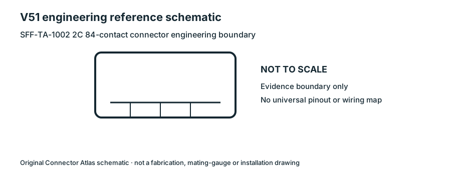
Orientation
V51 records the keyed card-edge/contact-count context only. Assignment side, lane, power and sideband roles must be resolved from the applicable platform specification; no universal pin map is reproduced.
Each value retains its exact example, role and measurement axis. Facts from different parts must not be combined into an invented component.
| Nominal contacts | 84S333Source-backed nominal position/contact count for identification: 84. Not a pinout or manufacturing drawing. |
|---|---|
| Contact rows | 2S912Named source examples retain separate role, part, view and axis limits; values are not a universal family specification. Rev1.6a 2C straight fixed receptacle; not right-angle/straddle variants. Documented role: socket. Standard drawing limits, not a measured specimen or exact manufacturer part.; A1 indicator shape is not transcribed as literal lettering. Manufacturer logo/series/part markings remain unknown.; Preserve existing application pinout records; mechanical drawing does not establish electrical usage. |
| Contact pitch | 0.6 mm longitudinal adjacent mating contact/pad centersS912Named source examples retain separate role, part, view and axis limits; values are not a universal family specification. Rev1.6a 2C straight fixed receptacle; not right-angle/straddle variants. Documented role: socket. Standard drawing limits, not a measured specimen or exact manufacturer part.; A1 indicator shape is not transcribed as literal lettering. Manufacturer logo/series/part markings remain unknown.; Preserve existing application pinout records; mechanical drawing does not establish electrical usage. |
| Dimensions / axis | 35.75 mm maximum overall longitudinal span; 6.15 mm maximum transverse body depth; 9.25 mm maximum height from SMT lead plane to housing topS912 · S912Named source examples retain separate role, part, view and axis limits; values are not a universal family specification. Rev1.6a 2C straight fixed receptacle; not right-angle/straddle variants. Documented role: socket. Standard drawing limits, not a measured specimen or exact manufacturer part.; A1 indicator shape is not transcribed as literal lettering. Manufacturer logo/series/part markings remain unknown.; Preserve existing application pinout records; mechanical drawing does not establish electrical usage. |
| Connector role | card-edge; socketS333 · S356 · S912Named source examples retain separate role, part, view and axis limits; values are not a universal family specification. SFF-TA-1002 card-edge connector variation Rev1.6a 2C straight fixed receptacle; not right-angle/straddle variants. Documented role: socket. Standard drawing limits, not a measured specimen or exact manufacturer part.; A1 indicator shape is not transcribed as literal lettering. Manufacturer logo/series/part markings remain unknown.; Preserve existing application pinout records; mechanical drawing does not establish electrical usage. |
| Keying / polarization | One off-center slot-divider keyS912Named source examples retain separate role, part, view and axis limits; values are not a universal family specification. Rev1.6a 2C straight fixed receptacle; not right-angle/straddle variants. Documented role: socket. Standard drawing limits, not a measured specimen or exact manufacturer part.; A1 indicator shape is not transcribed as literal lettering. Manufacturer logo/series/part markings remain unknown.; Preserve existing application pinout records; mechanical drawing does not establish electrical usage. |
| Recorded markings | Position A1 identification mark required by drawingS912Named source examples retain separate role, part, view and axis limits; values are not a universal family specification. Rev1.6a 2C straight fixed receptacle; not right-angle/straddle variants. Documented role: socket. Standard drawing limits, not a measured specimen or exact manufacturer part.; A1 indicator shape is not transcribed as literal lettering. Manufacturer logo/series/part markings remain unknown.; Preserve existing application pinout records; mechanical drawing does not establish electrical usage. |
| View convention | Mating-face view: B row above A row; position1 at right in the published straight-receptacle drawing.S912Named source examples retain separate role, part, view and axis limits; values are not a universal family specification. Rev1.6a 2C straight fixed receptacle; not right-angle/straddle variants. Documented role: socket. Standard drawing limits, not a measured specimen or exact manufacturer part.; A1 indicator shape is not transcribed as literal lettering. Manufacturer logo/series/part markings remain unknown.; Preserve existing application pinout records; mechanical drawing does not establish electrical usage. |
Not recorded: Positions / cavity span, Populated contacts, Contact gender / arrangement, Mounting, Coupling / latch, Shell / form, Manufacturer, Series, Exact part / implementation. Unknown fields stay unknown; illustrations supply no measurements or pin assignments.
Your next step
Source trail
SNIA REF-TA-1012 identifies the SFF-TA-1002 2C connector variation as an 84-contact connector with up to 26 differential pairs of data signals.
SNIA · SNIA REF-TA-1012 SFF-TA-1002 connector variations — 2C ↗
SNIA’s published reference describes the SFF-TA-1002 2C variation as 84 contacts with capacity for up to 26 differential data pairs in a GSSGSSG contact pattern.
Discovery Quality III